I have already described the actual receiving and transmitting, but I haven't mentioned a very important part of the chain without which my solution would work only at little distance. The antennas. Both the radio and the transmitter were equipped with one. As usual, not knowing anything about the subject matter, I turned to Google and a physics textbook. After some time of researching, I had an idea about what sort of an antenna I wanted to use for each device. I started with the one for the transmitter.
This antenna design came from a HAB project I encountered on the internet. It was a ground plane antenna made of just a coaxial cable and a few pins and straws. I had all the components at hand so I gave it a try.
First thing to do was to strip of the plastic cover off the coaxial cable. The cable was 50Ω RG58U. I chose this one because the NTX2's output is 50Ω as well. The length of the stripped part was 17.25cm, a quarter of the wave length at 434.65MHz
Then I uncovered the other end as well and twisted up the RG58U's copper shielding into two cords. The NTX2 had three antenna pins. Two for GND and one for signal output. I fitted the cords with KONPC-SPK pins including the core wire hidden beneath the insulation.
On the antenna end of the cable, I twisted the copper shielding up into four cords this time.
I would fit each cord into a straw and tape them to a foam board to create two perpendicular lines. This would form the ground for the active element of the antenna. The core of the cable would stick perpendicularly to the ground.
After that the antenna was ready for a test. I attached it to the breadboard using pins.
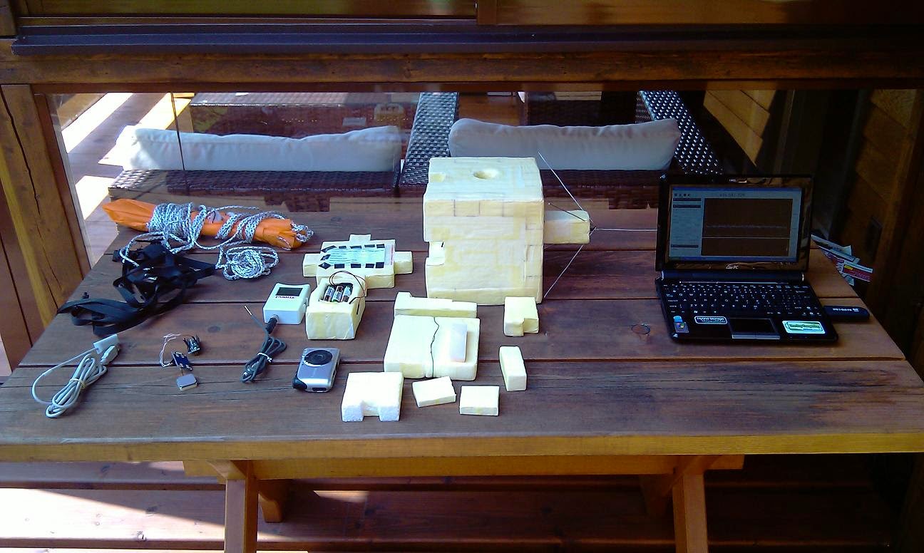
And here is the set at work. The signal viewed using the SDR visibly increased or decreased whenever I either attached or disconnected the antenna from the board.

When I was building the previous antenna, I exchanged several messages with people in a Czech Citizen Band Radio forum who were fairly critical towards this design and used components especially. I, not knowing what was sufficient for a HAB and what wasn't, decided to take into account their objections and construct a new antenna. This time, I would instead of a coaxial cable use plain copper wires. Also, I came across a neat piece of software that allowed me to design my antenna and provided me with a feedback on its final parameters. The reality is never as ideal as the theoretical model but at least I had a basis. The program was called MMANA-GAL and led me to the design in the image above. It was still a ground plane antenna, but this time, I bent the ground wires at an angle of 35° to the original ground. This would change the impedance of the antenna to 50
Ω and match it to the NTX2's impedance.
The parameters of this antenna design.
The radiation characteristic of the antenna.
And the dimensions of the antenna. The length of the active element was changed from 17.25cm to 16.4cm for 434.65MHz frequency.
Since I would have to solder the coaxial cable leading from the antenna to the NTX2 and I would have to securely attach the impractically shaped antenna to the payload box, I decided to redesign the box a little. The antenna and the NTX2 would have to stay in one piece, but I wanted to be able to work with it even without the box. Thus I came up with a solution that would comprise of carving out a hole in the bottom of the box and inserting the coaxial cable inside a squared log of polystyrene. I would then be able to fit this into the hole in the box or take it out again.
I used three copper wires. One for the active element of 16.4cm length and two for the ground of 34.4cm lengths. These two, I would then bend at an angle of 110° inbetween the two ends. I would solder them together and then to the coaxial cable's unwound shielding. To the cable's exposed core, I would solder the short copper wire.
To secure the antenna in position, I carved out four insections in the polystyrene and pushed the wires inside. Though, I should mention that in the end I decided to carve out the insections in the corners, because when positioned like in the picture, the wires were in the way when I wanted to lie the box on its side.
When tested, the antenna worked just fine allowing me to receive the signal with my notebook and SDR without its antenna at the other side of the garden. Something unthinkable with just the NTX2 alone.
Now, it was time to build the receiving antenna. Since the NTX2's manual states its reach to about 500m and I had to count with distances of about +50km, I had to look for directional antennas with as high a gain as possible. The positive side to the HAB story is that since the balloons fly above us, there is nothing in the way for the signal to reach us. The UKHAS website states a record breaking reception distance of 800.3km. And this was achieved with the standard 10mW transmitters. After a traditional research, I decided for a 9 element Yagi antenna.
The parameters of my Yagi. These are sort of reverse engineered, because I didn't manage to cut the elements exactly as the scheme stated, so I made this model to see what exact parameters the program predicts for my actual antenna.
The radiation pattern. The gain of 11.29 dB compared with a dipole sounded good enough to me.
And the dimensions of my actual antenna.
These were the dimensions for the individual elements as I got them from some Yagi design websites. Unfortunately, I made a terrible decision and bought 2.5 and 3mm steel sticks to use them for the elements as opposed to copper or anything less stiff and more compliant. The piece of paper also contains the proper spacing of the elements.
The list of components for the Yagi contained: two meters of Belden H121A coaxial cable of 75
Ω impedance (to match the impedance of the DVB-T dongle), two terminal blocks able to fix a steel stick of 3mm in diameter, one male TV aerial plug, one long enough wooden squared log (2.5 x 2.5cm) and two 1m long steel sticks 3mm in diameter and one 1m long stick 2.5mm in diameter. To clarify the choice of the material for the antenna elements, I have to say that at first I tried to get hold of some copper sticks, but failed to find any around my town. I came across suggestions to use welding sticks, but as I found out later, they sold them only in packages of 500 sticks. The only thing resembling my vision were these steel sticks sold in an RC model shop. Only later I found out how difficult it was to cut steel. One cut through the 3mm steel stick took me and my handsaw about ten minutes of unremitting sawing. The reason for one of the sticks being only 2.5mm in diameter was that they simply didn't have any more of those 3mm thick. This was the reason for me not being able to get the dimensions of the elements exactly right. The steel would often break off at the end of the sawing leaving crooked endings. Thus I ended up with most of the elements about 1mm shorter or longer.

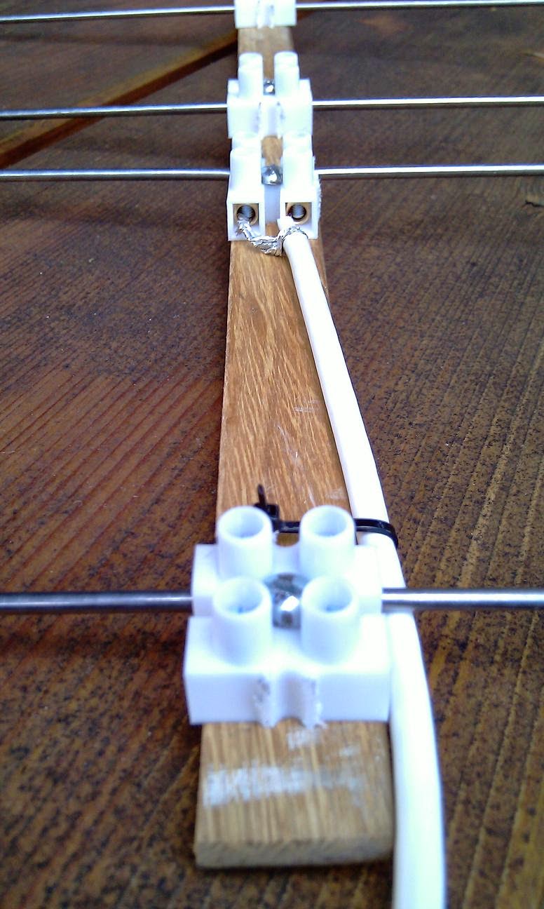
First, I went about making the dipole element. That meant sawing off two 16.25+1cm long pieces. That one additional centimeter is for the bend at the end as illustrated in the picture above. Each piece would then go to one dual terminal block and would be electrically connected to the coaxial cable at the other side. The end of the coaxial cable was stripped of the plastic coat, the shielding was wound together and put inside one part of the terminal block, and the remaining core wire to the other.
The other end of the coaxial cable, I fitted with the male TV aerial plug. But since the DVB-T dongle had a female MCX connector, I had to find an MCX to aerial plug adapter. With that done, the dipole was ready.
The other elements were simpler. All I had to do was to saw off the right lengths of the individual elements and than just fit them in the dual terminal blocks.With all the elements prepared, I marked the right distances between them onto the wooden log and screwed them down. I also used one strap fastener to secure the cable, so it doesn't rip out of the dipole.
Here is the finished antenna. I only replaced the wooden squared log from the previous pictures with one of appropriate dimensions to seat all nine elements. The whole antenna measured a little over 130cm in length. The picture on the right shows one of the first tests. The transmitter powered by a notebook and the signal being decoded on a PC.
With all the antennas and the transmitter ready, it was time for the first proper long distance test. I placed the transmitter on the top of the roof and drove off to one of the hills around my town with a decent line of sight. I set up the antenna and the receiver. You can notice that I had equipped the antenna with a handy tripod. Just a few wooden logs knocked together. The distance to the transmitter was 4.6km and the reception worked without a problem. After successfully finishing this test, I used a layman's logic. If it works at the distance of 4.6km, it will work at the distance of 30-50km as well.

Coincidentally, just today, I noticed a high altitude balloon being released in Budapest. Finally one close enough. The highest number of balloons is released in England, well beyond the reach of my antenna. At about the time the balloon was passing the 26th kilometer in altitude, I took out my antenna and notebook, set it up in the garden and directed it roughly in the right direction. After a couple of moments of fiddling with the settings, I managed to receive and upload 2 telemetry strings right before the balloon's burst. Additionally, I received several more partial strings, but with a lot of errors. Nevertheless, it was my first reception of someone else's payload, and it verified the functionality of SDR and my homemade antenna at the distance of 263km. I only wonder whether the issue with the other telemetry strings was a problem of the notebook not being capable of coping with the overload of data, or if it was simply at the limit of my antenna's reception ability. I did have to aim it through a group of trees after all. I guess only more reception attempts and more work experience with the equipment may answer that question.