Alongside working on a new tracker, I thought I could upgrade the receiving side of my equipment as well. And so this blog will document that endeavour. My initial objection was against my 9 element YAGI's length which made it difficult to fit inside a car. Browsing the web for a replacement candidate, I came across a HELIX antenna that caught my eye. Promising sufficient gain, wide bandwidth and circular polarization (which might help with a constantly swinging an moving payload) I got my winner. I also liked it visually and wanted to try working with something more than just a bunch of rods.
First I modelled it in 4NEC2. I decided for 4 turns of 23.1cm in diameter each with 17.43cm spacing as the antenna was intended for 434MHz. The reflector was an octagon measuring 55cm from side to side. From reflector to the end of the helix the antenna measured 69.7cm while requiring 298.6cm of tubing for the helix. The picture above shows the model of the antenna in free space.
With a real ground added to the model (the antenna hovered 1.3m above ground), the expected radiation pattern changed a little increasing gain in the forward lobe from 11.7dBi to 15.9dBi.
I also tried modelling the antenna at an angle (45°) to get some sense of what it would do to the radiation pattern.
The last model shows the pattern for the antenna pointing directly upwards. Based on other people's experience with real life helix antennas I'd take these calculated gain numbers with a grain of salt.
For the helix I used 3m of 6mm hand bendable copper tubing. The reflector utilized 55x55cm of 1mm aluminium plate. The skelet was made of wooden rods and a square log.
This way of mounting asked for a few pieces of plastic tubing to hold the wood together where the screws went in.
The rods fit the drilled holes precisely and didn't need any additional fixing or gluing.
Hand bending the copper tubing to fit the exact dimensions took quite some time but in the end the result was satisfactory.
With scissors for cutting metal shaping the reflector was just a matter of minutes.
At this point, it became obvious that the antenna was going to be quite heavy. Something I hadn't considered.
Nevertheless, I went on with the assembly.
The helix was soldered to an SMA female connector that was bolted down through the reflector.
As for matching the antenna, I came across an easy method called Wavetrap (described in this thread
IBCrazy's Wavetrap). All that was necessary was to cut a rectangle (I used a piece of copper plated PCB material) of 1/8 wavelength by 1/16 wavelength and solder it to the helix starting at 1/16 wavelength from the connector. For 434MHz the dimensions used were 8.64 x 4.32cm and starting at 4.32cm from the connector.
As I mentioned, the weight of the antenna made it impossible to use it with just a tripod. Here it is fitted with a temporary solution, but I am yet to come up with something more reasonable.
That led me to reconsider using a YAGI again, but this time just a small, more utilizable one. My former yagi was just a coax cable attached straight to the driven elements. This time I thought I would look for a properly matched design.
I started by modelling the thing in 4NEC2 again. This time I tried including the aluminium tripod in the model as well to see what impact it would have on the radiation pattern. I decided for just 3 elements to make it easy to carry and use on foot. The initial dimensions were 36.2cm for the reflector, 36.2cm for the dipole and 33.0cm for the director. The spacing between the director and the dipole was 4.8cm and 12.1cm between the dipole and the reflector.
For comparison, I modelled it in vertical polarization configuration as well. That decreased the gain in the strongest forward lobe from 12.6dBi to 11.3dBi. Once again I had reservations about seeing these numbers in the real world.
The materials used for the construction were 2.5mm brass rods for the elements. A wooden square log for the support.
Then 2 pieces of 75Ω coaxial cable 1/4 wavelength long. These were soldered in parallel (as described in
The DK7ZB Match for Yagis) to accomplish a 37.5Ω line impedance to match the Yagi's expected 28Ω impedance to the standard 50Ω impedance.
A female SMA connector on its mount that I made out of the remaining aluminium bits and pieces I had from the Helix antenna.
I needed something to hold the driven elements since they couldn't be held in place by running them through the wooden mount like the other two. I had to improvise a little bit and cut this piece of plastic out of a scrap soap dispenser.
The main frame was done. Time to solder the remaining bits.
A look on the final implementation of the matching bit and the connector.
The completed antenna.
Having the 70cm band secured, I turned my attention to the 2m band since I had been interested in APRS for quite some time and I intended to equip my upcoming tracker with APRS capabilities as well.
I didn't want to do anything special here. Just a simple DIPOLE. Once again I tried modelling it first to get a grasp of the radiation patterns. First in vertical polarization mode.
Second in horizontal polarization.
The used materials were very similar to the yagi. Only the brass rods were 4mm in diameter this time. Since the rods were sold in 1m lengths, I simply cut one in half.
To mount the rods on the wooden square log, I used a similar solution to the yagi one. However this time, I had to add a few reinforcements since the rods were somewhat heavier.
With the antenna in my room and after some fiddling about with SDR#, the packets from nearby stations started to decode.
Another thing I added to my setup was a low noise amplifier built around ERA-3SM+. The datasheet promised DC-3GHz bandwidth with gain of 23.4-16.4dB across this range. Based on the specific parts I chose, the range of my implementation should be between 17-480MHz. For anyone interested:
LNA v1.0.sch and
LNA v1.0.brd.
Newly I noticed that the PCB manufacturer OSH Park offered the lowest price for a small order of 3 boards. In combination with free shipping the cost for these boards was about $5 while the delivery took about 3 weeks to the Czech Republic (based on the post office I assume they manufacture in the US).
As can be seen on the antennas and here on the LNA, I decided to utilize SMA connectors on all of my setups. There are all sorts of variations on EBAY for a reasonable price.
Here is the LNA almost complete. It was an opportunity for me to practise SMD soldering with a hot air soldering station for the first time. I had to, because I knew I would have to tackle much more soldering of tinier components on the upcoming tracker.
One thing that kept bothering me about the antennas was that I didn't have a clue whether they were tuned to the frequency I intended them for. I had seen people using expensive antenna analyzers, vector network analyzers, a few to improvise with an oscilloscope and a directional coupler, but all these options were out of my reach. A bit of googling eventually led me here:
SWR meter - Do it yourself project. The thread describes a simple diode probe that in conjunction with a directional coupler and a voltmeter can measure the forward and reflected voltages between a transmitter and an antenna. The original device was intended for FPV stuff in the 1.2, 2.4 and 5.8GHz ranges, but I thought I could try replicating it for the 434MHz band. First I ordered this directional coupler that was supposed to work for 1-1000MHz.
Second I soldered up the probe. A 1kΩ resistor, a 100nF capacitor and a diode. Here I had to choose a different model, because the HSMS-286 from the original thread was designed for 915MHz-5.8GHz range. I went for HSMS-2820 instead.
Next I needed a transmitter. It turned out that despite being a crap high altitude balloon tracker I could have another job for my TT7-40. The RFM22B provided a band of frequencies between 413 and 490MHz which I could use for a sweep.
A couple of modifications later (an SMA connector on the output of the transmitter, two Ublox pads used for serial communication) I had something useful.
The programming and communication now utilized a USB to TTL converter and didn't require the SPI interface. The original device used a voltmeter to measure forward/reverse voltage at one frequency. I thought I would program TT7-40 to quickly sweep a whole band of frequencies and measure the diode's output via an analog input of the ATmega. Then output the data on the serial port. I wrote the script quickly in Arduino IDE so for anyone interested:
TT7_40_SWR_Meter_1.ino.
To test an antenna one would connect the RFM22B to the IN port on the directional coupler, the antenna to the OUT port and the probe to the CPL port. That would measure the forward voltage at a specific frequency. Then one would switch the ports (IN - antenna, OUT - RFM22B) and measure the reverse voltage. Using the formula:
SWR = (1 + REVERSE / FORWARD) / (1 - REVERSE / FORWARD)
One would arrive at the Standing Wave Ratio of the system at a specific frequency. Sweeping a band of frequencies, one could draw a curve and possibly see it dip indicating the frequency the antenna was tuned to.
I took the antennas and a tripod outside and started with the yagi. I intentionally made the driven element a little longer so I could shorten it while measuring the effect on the SWR curve.
Here are the curves for 6 measurements I made indicating the length of the driven element. I didn't rely on the absolute value of the numbers with this cheap approach too much and rather focused on the progression of the curve. The blue curve representing the original dimension seemed to dip towards the left side of the spectrum as expected for an antenna electrically too long. So I started cutting and observing the dip moving towards my intended frequency. However, after the fourth cut (second blue) the driven element was now shorter then the director and the frequency response deformed. Afraid I cut too much, I shortened just the director and saw the dip (orange) to appear at 442MHz. Apparently, I was too eager with the cutting and ended up with a not exactly tuned antenna.


I also, perhaps to late, realised that it would have been better to do the measurements at the antenna without the addition of 3m of coaxial cable. I at least made one for comparison. If the numbers were any good in an absolute sense, at 434MHz I might have still been at 1.71:1 SWR. Unfortunately, I didn't have any other meter for reference so, who knows with this thing. The final yagi dimensions were 362mm for the reflector, 310mm for the driven element and 314mm for the director.
I also modelled it again in 4NEC2 to see the impact of the cuts on the radiation pattern.
The helix underwent the same test, however, I initially couldn't measure any reverse voltage. Only after I added an amplifier at the probe's output, I could get something out of it. I am not sure how to interpret this result. A helix promises a wider bandwidth, so to deduce something out of this I would probably need a wider sweep than just 413-490MHz.
Just to see what would happen, I tried sweeping a simple piece of 148mm wire stuck inside the SMA connector. Considering it to be 1/4 wavelength long would make its resonant frequency to be at 506-7MHz which is towards what the incomplete curve seems to be dipping.
One last thing to do was to verify that the antennas could actually receive something at a distance. I placed a transmitter in the garden and set off to my traditional testing spot about 4.7km away.
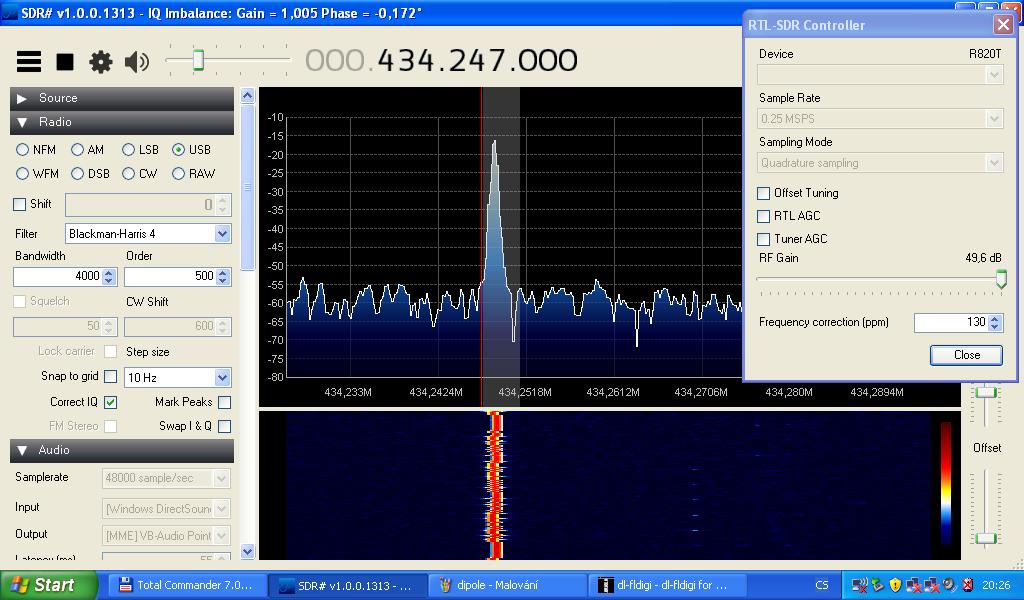
The 434MHz signal was nice and strong with the yagi.
Having no other means of testing the LNA's performance but with an actual signal, I tried plugging it in. Unfortunately, it seemed that the LNA instead of increasing the signal mainly just increased the noise floor. Perhaps I should have made it with a bandpass filter for just a narrow bandwidth.
The dipole performed somewhat worse, but that was expected since it was designed for a different frequency.
The LNA's impact on the dipole was similar to the yagi.
For comparison, I tried plugging in the standard whip antenna that comes with the SDR dongle. Its performance was comparable to the dipole's.
Last but not least the helix antenna.
After connecting it, it was immediately evident that the helix had the biggest gain of them all.
And the LNA's effect.
In summary, I gained three new antennas. Two are proven to work and ready to be used (yagi and dipole).
The third one (helix) works nicely as well, but I will have to come up with a sensible way of mounting it and I will reserve it for home use.
On the other hand the accuracy of the antenna analyzer would deserve some comparison to know what to think about the data.
And the LNA might benefit from further testing and tinkering about as well.