This blog post is the third instalment of my notes on making superpressure balloons. The previous posts can be found
here and
here.
| TR9 |
| layers |
PE / PA / EVOH / PA / PE |
| width |
1.35 |
m |
| length |
60 |
m |
| thickness |
40 |
μm |
| density |
0.972 |
g/cm3 |
| square weight |
38.9 |
g/m2 |
| tensile strength (MD/TD) |
>30 / >26 |
MPa |
| elongation (MD/TD) |
>400 / >450 |
% |
| sealing temperature |
125-160 |
°C |
| price |
~91 |
€ |
After putting together a couple of new
trackers, I thought I would try to make some improvements in construction of the balloons that would carry them as well. I did a fresh search for suitable material manufacturers, but to no avail, so I at least ordered a roll of slightly thinner (40μm) film from the same manufacturer as previously. Datasheet specs can be found in the table above. For anyone interested, as there have been requests, the manufacturer is Vepak, s.r.o. based in the Czech Republic and the film is called TR9.
TR9 is said to be a transparent 9-layer co-extruded blown film typically used as a food packaging material. The datasheet mentions only two polyethylene (PE), two polyamide (PA) and one ethylene vinyl alcohol (EVOH) layers leaving the remaining four slots for some sort of tie or undisclosed layers.
Literature suggests ethylene acrylic acid (EAA) and anhydride modified polyethylene (AMP) as possible adhesive materials to tie the layers of PA and PE which otherwise do not bond well. The EVOH to PA bond, on the other hand, is said to not need additional adhesives. Unfortunately, the manufacturer doesn't go into any of these details, so the above illustration is only my best guess of the structure. The total film thickness is 40μm with a 10% tolerance. There is no further information about the thickness of the individual layers.
A design of a blown film co-extruder, the machine responsible for production of these kinds of films, can be seen in the image above. Solid pellets of the raw materials are fed to separate extruders which melt the polymers and forward the melt to a main die. Inside the die, the melts from individual extruders are stacked, layer upon layer, to form the resulting film structure. The stacked melt output by the annular die is guided upwards to the top of the tower while being cooled down and blown to desired dimensions (width and thickness) by air. At the top of the tower, the solidified film is flattened and conveyed back down by a system of rollers. The edges are cut, and the resulting two continuous sheets are wound on rolls. There are a number of videos on Youtube that show different parts of the machines at work.
The image above illustrates the flow of individual polymer melts inside a die - input from extruders at the bottom, multilayer stacked output at the top. For an interesting insight into the state of the polymer film industry, see this series of articles (
one,
two and
three) which goes into the older 3/5-layer lines and compares them to the more modern 7/9/11-layer films produced these days. This
paper then discusses technological concepts for production of up to 100-layer films as well as the contemporary die designs.
Polymers. Polyethylene, polyamide and ethylene vinyl alcohol, the materials from which TR9 is extruded and blown, are synthetic polymers - large molecules in the form of long chains of a basic subunit created via
polymerization.
The above is a formula of a polyethylene (
PE) repeat unit. Polyethylene is a thermoplastic - a polymer that can be repeatedly melted and recast. As a nonpolar polymer (unpolarized molecule), it is difficult to bond to other materials such as PA and EVOH without a tie layer. Polyethylene comes in several
classes based on its density and branching (additional chains of subunits connected to the main chain). In case of barrier films, it is typically linear low-density polyethylene (LLDPE). It has a semi-crystalline structure (35-60% crystallinity - the degree to which the molecular chains in the material are aligned versus randomly entangled chains). A layer of polyethylene is utilized for its lower melting temperature as the bonding surface between two sheets of film. During heat sealing, chains from both sheets entangle across the seal interface, while intermolecular bonds reform as the weld cools down.
Polyamide (PA), typically nylon
6 or
6,6 (repeat unit formula of nylon 6 above), is a symmetric and polar polymer with semi-crystalline structure (35-45% crystallinity). The polarity and molecular symmetry allow bonding between individual molecules via hydrogen bonds which contributes to strength and rigidity of the material. As a part of a multilayer film it is used for its higher strength and oxygen barrier properties. Like polyethylene, it is a thermoplastic, but melts at a higher temperature.
Ethylene vinyl alcohol (
EVOH) is a copolymer derived from two monomers - ethylene and vinyl alcohol. It is a semi-crystalline polar thermoplastic polymer. Its high degree of crystallinity (58-70%) and the percentage of ethylene content determine the material's barrier properties. Lower ethylene content leads to better barrier properties, while higher content to lower extrusion temperature. The barrier properties are the main reason for incorporating it in a multilayer film. The same barrier performance can be achieved with a much lower film thickness than in case of using other polymers. In terms of a balloon, it keeps hydrogen or helium inside and air (N
2, O
2) outside of the envelope at a comparatively lower mass due to the lower layer thickness.
|
PE |
PA |
EVOH |
| Formula |
(C2H4)n |
(C6H11NO)n |
(C2H4O-C2H4)x |
| Tg [°C] |
-110 |
60 |
48-72 |
| Tm [°C] |
110-130 |
193-260 |
156-195 |
| UTS [MPa] |
10-37 |
48-112 |
37-74 |
The table above contains basic information about the individual materials such as the glass transition temperature $T_{g}$, the melting temperature $T_{m}$, and the ultimate tensile strength $UTS$. The source of the data is
matweb.com, specifically an overview of materials listed in the database under LLDPE, Nylon 6 and EVOH. It is apparent from the values that both at room temperature and temperature at flight altitude (-40°C to -70°C), the polyethylene layer of the film will operate above its glass transition temperature, while the nylon and EVOH layers will operate below theirs. The
glass transition occurs in amorphous polymers and amorphous regions of semi-crystalline polymers. Below the glass transition temperature, the polymer chains don't have enough energy to move, they are interlocked with each other, and the material is rigid, hard and brittle. As the temperature increases above the glass transition level, the chains are able to slide past each other when a force is applied, and the overall material becomes soft and flexible.
In general, polymers are long chains of repeating strongly bonded (covalent, ionic bonds) subunits. The length of the chains (degree of polymerization) through weaker intermolecular forces acting between neighboring chains and through chain
entanglement influences the physical properties of the resulting material. For example, increasing chain length leads to increased strength, toughness and glass transition temperature. A factor playing a role in chain entanglement is
branching of the polymer chains, a situation where other chains covalently bond to a main chain to create the polymer molecule. Long branches may again increase strength, toughness, and T
g, while short asymmetric branches may reduce the ability to entangle or bond with other molecules, thus decrease the listed properties. As a polymeric material solidifies from the original melt, depending on the specific polymer and parameters such as cooling rate, it may stay in a form of irregularly entangled chains (amorphous polymer), or it may began forming regions of aligned and folded chains (semi-crystalline polymer). The degree of
crystallinity again influences the material properties. Higher content of crystalline regions is responsible for higher hardness and brittleness, while elasticity is the domain of amorphous polymers.
When semi-crystalline polymers are subjected to tensile stress, the chains in the amorphous regions elongate, the crystalline regions rotate to align with the applied force, then with increasing stress the individual lamellae (ordered crystalline regions) begin to fragment and slip. Up to a certain point, the deformation is elastic - the piece of material returns to its original dimensions when the force tensing it is removed. Beyond that point, the deformation is plastic - permanent. Plastic deformation due to stretching of a semi-crystalline material leads to partial alignment of polymer chains in the direction of the force. The result of the alignment is an increase in strength of the material.
Due to the nature of the interactions and molecular structure outlined earlier, a polymeric material is said to be
viscoelastic. When it is subjected to constant stress, the material creeps - a continual increase in permanent strain even below the stress needed for plastic deformation. When the material is fixed at constant strain, it undergoes stress relaxation - an observed decrease in stress over time. As already mentioned, temperature is an important factor in all these interactions. An interesting property of viscoelastic materials associated with temperature is the
equivalence of time and temperature. In practice, this means that a piece of material stretched at room temperature and a high strain rate will behave as if it was stretched at low temperature - it would be stronger and more brittle - or if it was stretched at a very low strain rate, it would behave as if it was stretched at a higher temperature - in other words, the material would be more ductile and elastic.
One other property that relates specifically to high altitude balloon envelopes is the material's sensitivity to UV radiation. Various sources state that the intensity of UV radiation increases with altitude between 10 to 12% per 1000m. That suggests that the material is exposed to 2-3 times higher intensity at expected float altitudes (10-16km) than it is at the surface. Polyethylene is
said to be - through breaking of the carbon and hydrogen bonds, and the resulting free radicals breaking the PE chains - susceptible to UV degradation which means the envelope will deteriorate over time.
Assumptions/Expectations (based on general behavior of polymers):
- Slow and careful pressurizing of an envelope at room temperature (pre-stretching) will possibly increase the strength of the material.
- The envelope material will be stronger at float altitude due to the low temperatures.
Quality control. Birefringent properties of a mechanically stressed plastic film turned out to be a useful tool throughout the work on new balloon envelopes.
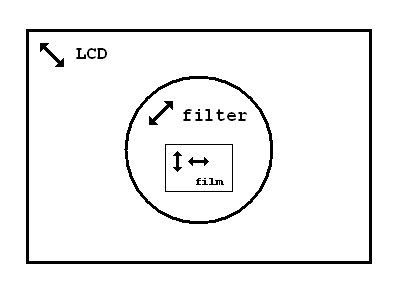
Photoelastic stress analysis utilizes the fact that the birefringent material has a refractive index dependent on the polarization of the light transmitted through the material, and that the size of the refractive index at each point is directly proportional to the size of the mechanical stress at that point. In combination with a source of polarized light and a polarizing filter, a color pattern which captures the instantaneous mechanical stress within the material can be displayed.


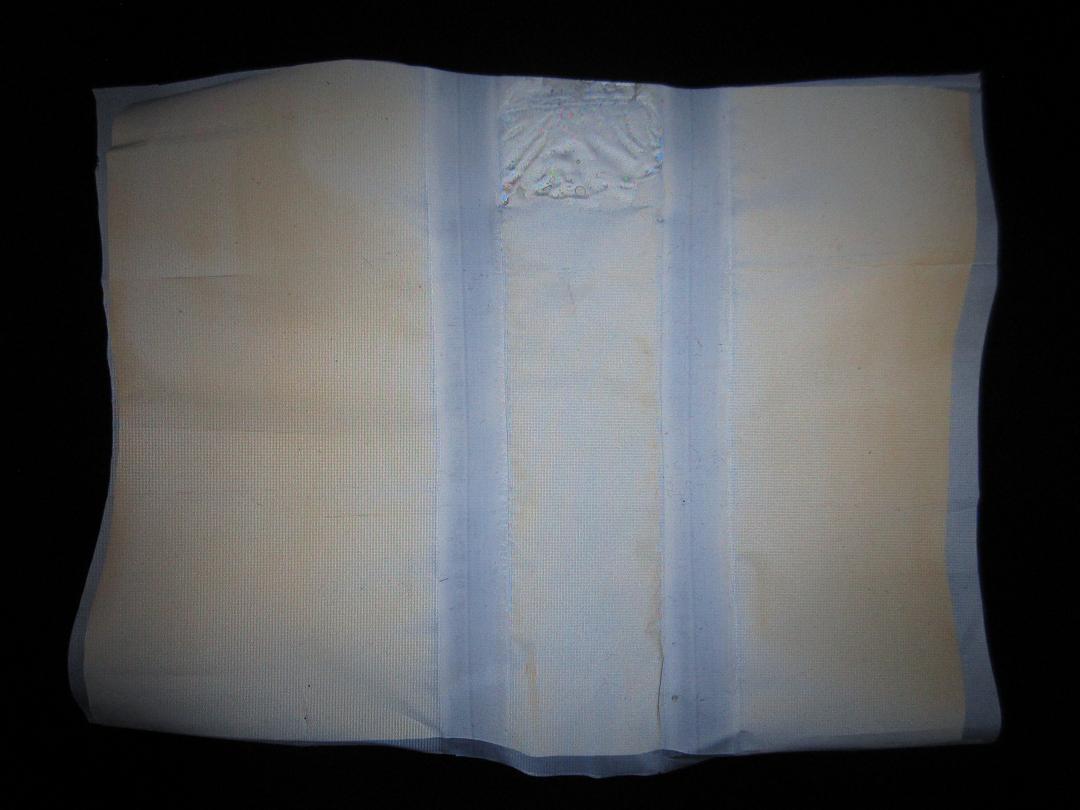
It turned out that the film itself acts as a polarizing filter to an extent in both the machine direction (MD) and the transverse direction (TD). In the first image, the film is oriented at a roughly 45° angle to the polarization of the light source and further 45° degrees to the polarization axis of the filter which itself is perpendicular to the light source. In the second image, the film is oriented to align with the light source in the machine direction and with the filter in the transverse direction. Because of that the light is blocked except for the corner piece intentionally folded at an angle to form a transitional filter between the two perpendicular polarizations.
A schematic representation of the setup used to acquire the previous images can be seen above. The polarizations of the source light, the filter and the piece of film are all indicated. The method was utilized in the following instances:
- Inspecting the sheets of film for defects prior to cutting individual balloon shapes. Particularly the upper layers of a film roll are often damaged from transportation and handling.
- Checking the individual welds after the envelope was heat sealed.
- Highlighting material imperfections and deformations after the envelope was pre-stretched.
An example of the effect is illustrated in the images above. As a rectangular piece of the film is stretched in hands, it unevenly plastically deforms impacting the local refractive indices. The images capture three degrees of increasing strain. The polarizing filter is oriented to block the polarized light source. The white light incident on the material decomposes to two orthogonal components each travelling at a velocity in accordance with its own refractive index. When exiting the material, the components recombine resulting in a new polarization (further description of the
principle). Since the effect is wavelength dependent, individual wavelengths undergo differing phase shifts between the components, hence the recombined rays suffer different degrees of extinction when they pass the polarizing filter. The result is a color pattern reflecting the degree of strain in different parts of the piece of material.
Heat sealing. A balloon envelope first starts as two or more sheets of the film cut out to specific shapes. The separate sheets are then heat sealed together to form an airtight envelope with a gas inlet.
The tool used in making the following examples and later on the actual balloon envelopes is a custom heat sealer described in detail in an earlier blog
post. As the shapes requiring heat sealing may be diverse, there are a few different types of welds and potential issues to be aware of.
Most commonly, there is a need to heat seal a circular shape along its circumference. The roundness is achieved by overlaying straight welds at a certain angle to each other. Only a part of the heating wire is typically used to make the weld. The image above illustrates the round weld. Both this image and the following images were taken through the polarization filter. The varying color spectrum between images is due to the orientation of the filter as some features are easier to highlight this way while other with the filter reoriented.


Some balloon shapes require making long straight welds. Since the heat sealer's wire has only a limited length (345mm), a series of straight welds have to be conjoined and aligned. A slight issue arises from the fact that the film tends to melt a little too much at the ends of the pressure bar pressing the film onto the wire. Because of that, I let the welds slightly overlap to avoid concentrating the excess melting in one spot. Illustration of the phenomenon can be seen in the images above.
The same issue is encountered when making corner welds necessary for the balloon's gas inlet. In this case, though, the melted end of the weld is exposed to the inside of the balloon and will be subjected to stress due to the envelope stretching. The welds are positioned in a way to minimize the melted area that would be exposed to the stress as can be seen in the images.
This image shows what happens when there is not enough pressure from the pressure bar at the end of a weld. The heat sealed area tends to warp creating spots with concentrated stress which can develop holes when the envelope is pressurized and the material stretched. Care must be taken when pressing the film with the pressure bar to distribute the pressure evenly.
Another issue with the weld endings is that the heat tends to spread beyond the end of the pressure bar and partially seal the two film sheets. It is a problem, because it can result in unintentionally sealing the gas inlet as can be seen in the images above.
An approach I have adopted to limit this adverse effect is to use a couple of pieces of a teflon tape (in both cases two pieces taped to each other) placed one in between the two sheets of film and the other between the film sheets and the wire as can be seen in the images above. This tends to contain the sealing to more or less where it was intended. In general, the weld endings are quite sensitive areas most prone to developing holes as the envelope is stressed and stretched if made poorly.


I also use a similar approach when making the long straight welds. This time with the teflon pieces either side the pressure bar between the film sheets and the wire. Originally, the heat sealer was occasionally as far as melting the film at the very ends. It turned out that the heating wire wasn't laid on the cement-bonded particle board beneath it all the way to the end of the sealing area and as a result, it was running a bit too hot there. This also made me shorten the pressure bar by a few millimeters.

Some larger envelope designs require heat sealing more than just two sheets of film. The image above shows a weld of four sheets of film. First, two sheets were heat sealed together with one of the yellow vertical welds, then the other two sheets with the other vertical weld. Both resulting sheets were opened, laid facing each other, and heat sealed together creating the multilayer horizontal weld - yellow parts represent four layers heat sealed together, white parts standard two layers.
Sometimes when finishing the overall weld, there is an excess of film from one of the sheets. In such a case, the excess film is folded and heat sealed as a four-layer weld.
Glue. The balloons I have been working on are intended for the
TT7B tracker. Since part of the tracker is a pressure sensor and a thermistor that are intended to be sealed inside a balloon envelope, I had to come up with a way to accomplish this.
It is not possible to make an ordinary weld over the cable, because the cable's dimensions leave the film close to it unsealed. The other option was filling the balloon's inlet with glue. However, polyethylene is due to its non-polarity often mentioned among surfaces to which most glues don't adhere. The ones that do list PE, such as the Loctite All Plastics I used, are typically two part - a surface activator and the glue.
This is a 20mm test inlet (it must be wide enough for the sensors to pass through) in the image on the left. The image on the right shows a cured blob of the glue sealing the inlet at the top. It is easier to discern the glue in the black and white rendition. A few drops of the glue put under pressure filled the whole space making the seam airtight.
The cable is composed of 8 strands of thin magnet wire wound together. Following the same approach as previously, this time with the cable inside the inlet, had the same effect. The inlet was sealed airtight and it was impossible to pull the cable out. The polarized light, then, provides a useful means of optical control.
These images come from a test balloon where a secondary inlet was glued airtight with a test cable inside, while a primary inlet was used to pressurize the balloon to test the seam. No leakage was registered during a 12 hour test at an inner pressure of 1800Pa. Care must be taken, so the glue doesn't creep along the wire to inside the balloon when pressed while curing as it is partially visible in the images.
Envelope types. Since the motivation behind designing the TT7B tracker was to collect information on balloon behavior, I decided to make a few different envelope types, so there is some comparison.
This is a basic schematic of the three envelope types that were made. The first type utilizes the full width of the film roll to give rise to a
Mylar balloon shaped envelope made of two circular sheets 1.35m in diameter. The second type then just separates the two semicircles with an additional piece of rectangular sheet 1.0m in length to create a tube shaped balloon. The third type is again a Mylar balloon shaped envelope, but this time made of four semicircular sheets with an overall diameter of 2.04m.


These are the heat sealed envelopes prior to pre-stretching. Including the time spent cutting out the shapes, it took a couple to a few hours depending on the specific size to make one of the envelopes. The blog post detailing the custom heat sealer ended with a description of a heat sealing procedure - sealing, cooldown and idle durations to ensure consistency among individual welds. When making these envelopes, I roughly followed that procedure. In practice, arranging the next weld occasionally took a little longer at which point I compensated with a little longer sealing duration, all based on the reported wire temperature. The specific parameters moved between the following values: input of 13V (7.3-7.7V across the wire) - fixed, heat sealing duration of 10.0-12.5s, cooldown period with film under pressure of 10-12s, and the period between individual welds of 60-120s.
Pre-stretching. The sealed envelopes undergo pre-stretching, a process of inflation and slow increase of pressure inside the envelope. A description of a programmable pre-stretching rig I built for this purpose can be found in an earlier blog
post.
Reasons for pre-stretching:
- Verifying the strength of the welds, and that the envelope was sealed airtight. In this case, the envelope can be inflated rapidly so the high strain rate makes the material behave as if it was at a low temperature - strong and brittle.
- Increasing the inner volume of the envelope. Larger inner volume leads to lower internal pressure caused by the same amount of gas needed to lift it which consequently decreases tensile stress within the material (despite the film becoming thinner).
- Increasing the strength of the material by forcing polymer chain alignment within the material.
- Releasing potential stress concentrations from the material and edges around welds. In this case and the previous two, the envelope is pressurized carefully even just held at a specific pressure level so the strain rate is very low, and the material behaves as if it was at a high temperature - elastic and yielding at low stress.
At float altitude, the balloon is permanently pressurized with the inner pressure increasing during the day and decreasing again during the night as the temperature of the gas changes with solar irradiation. The key difference between the inevitable stretching during a flight and pre-stretching is in the conditions. The ability to control the temperature, the pressure and implicitly the strain rate allows changing the material properties from strong and brittle to soft and elastic. In practice, maintaining constant pressure in an expanding envelope leads to increasing stress in the material. In other words, just keeping the envelope at a specific pressure equates to a low strain rate due to creep. The pre-stretching pressure levels must be chosen carefully. Otherwise, the creep rate at room temperature may be quite high. For example, the smallest envelope type pre-stretched at 1800Pa may expand its volume until it developes a tear in just a couple of 10s of hours.


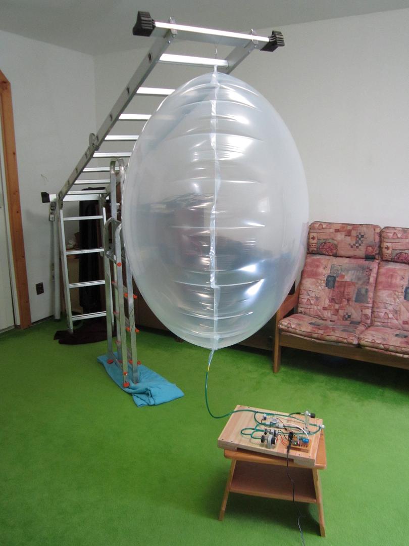
There was one other novelty since my last attempt at stretching balloons. Noticing that visible permanent deformations of the material - stretching marks - typically developed unevenly between the two sides of an envelope based on which side it was laid on the ground, the pre-stretching was done with the envelope hanged in midair this time to distribute the pressure evenly between the hemispheres.
The pre-stretching leads to deformations within the material. The polarized light is ideal for inspecting the envelope and observing the artifacts that develop. The following is a summary of what I've encountered.
This is a perfectly holding weld without any signs of loosening after the envelope was pre-stretched. As the shape of a pressurized envelope tends to round out, the material along the straight welds locally deforms to accommodate to the new shape.
This, on the other hand, is a long straight weld spanning across the most stressed area on the largest envelope that opened by a couple of millimeters, and the previously heat sealed material began to stretch.
Another defect of the long straight welds can be seen in the images above. This happens when the heat sealer melts the material too much at the ends of the heating wire. This weld still kept the balloon sealed, but its width was severely reduced.
The image on the left, on the other hand, shows an extreme case of this defect where the weld eventually completely ruptured. The image on the right, then, illustrates a well-done case of conjoined straight welds.
These images illustrate how stress is distributed around the gas inlet. Too much melting in the inner corner and the film will develop a hole as it stretches. This specific inlet is basically as best as it gets case with the heat sealer I use.
These are the multilayer welds after pre-stretching. The four layer weld of the largest envelope on the left holding perfectly. The folded excess film on the right showing a slight loosening in the corner.
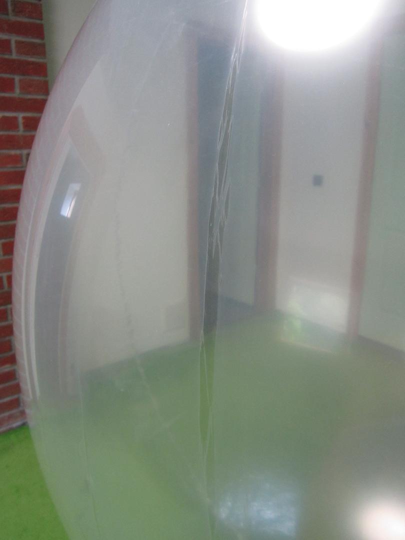
These two images show deformations in the most stressed area of a Mylar shaped envelope - the center of the circular sheet; if the circumferential weld was the equator, then the areas in question would be the poles. The visible vertical lines correspond to the machine direction (MD) of the film - the direction in which it was drawn from the die and later wound on the roll. The image on the right shows an early sign of a stretching mark developing.
A few images of the previously mentioned stretching marks can be seen above. The first two images show a progression of this deformation as the envelope is stretched further. The third highlights the novel nature of the material in these areas on a slightly deflated envelope. Based on the properties of the individual layers described earlier, and the fact that the surface in these areas is different to touch, my guess is that it is the low strength polyethylene layers that ruptured. Also heat sealing a piece of film that was already stretched typically leads to very weak and prone to fail welds.
These images show the stretching marks on a deflated envelope under polarized light. The first two capture two different areas on a balloon at different degrees of stretch. The envelope was cut into pieces for the bottom two images, so they show the polarized light shining through a single sheet of film hence the different colors.
I've also encountered localized defects, as can be seen in the images above, that would eventually develop into a hole, and the envelope would fail. This, however, was only the case of the older 50μm film. I haven't come across this issue on the new 40μm film so far.
These images illustrate cases of excessive stretching on a couple of test envelopes. The balloons developed defects such as significant stretching marks, the envelope unevenly bulging, or a long straight weld rupturing at the peak of the bulge. The first balloon was stretched to 1.36 times its original volume, the second balloon to 1.42 times its original volume.

This chart contains logged pressure data from pre-stretching of six balloon envelopes. There are always two envelopes per balloon type (circular shape 1.35m in diameter, circular shape 2.04m in diameter, and obround shape 2.35m in length). In each case, one envelope was used as a test to get some sense of how quickly and at what pressure levels the material expands. The second envelope, then, was pre-stretched more carefully with intent of using the envelope on a flight. A criterion in pre-stretching the flight envelopes was allowing them to expand mildly and without developing stretching marks. Also note that the applied pressure levels are lower than in case of the TT7F balloon
envelopes, because the material was thinner this time (40μm vs. 50μm).
Finished balloons. Three envelopes, one per each type, were prepared for a series of upcoming flights in the end.
These are a couple of images of the envelope making process. One balloon being stretched, another envelope being sealed, and more cut-out pieces waiting for their turn. The envelope making process in steps:
- Examining a sheet of material with polarized light and filter.
- Cutting out individual shapes from the sheet for a specific envelope and heat sealing them.
- Examining the finished welds with polarized light and filter.
- Hanging the envelope and inflating it to couple hundred pascal to measure its volume.
- Pre-stretching the envelope.
- Deflating the envelope and inflating it again to measure its post-stretching volume.
- Examining the envelope with polarized light and filter.
The smallest 1.35m circular envelope showed no issues with the welds, nor any other artifacts. It was also the one that registered the largest volume increase prior to developing the first stretching marks.
In case of the 2.35m obround envelope, relatively early appearance of the first stretching marks meant only a limited increase in volume compared to the test envelope. The only issue with this type of balloon occurred on the test envelope where a long straight weld ruptured after extreme stretching and bulging (discussed earlier).
The largest 2.04m circular envelope couldn't do without some issues with the long straight welds spanning across the area of highest stress. It also registered the least volume expansion prior to appearance of the first stretching marks.
Despite my best efforts, the heat sealer melted the very ends of the long straight welds a little too much again. I at least bent the material in such a way that there is enough of quality welding between the inside of the balloon and the melted spots. The issue is that unlike in case of the obround envelope, the long straight weld spans across a highly stressed area on this type of envelope. Nevertheless, I intend to test flight this envelope and rely on the remaining thickness of the welds.
| Envelope |
Vorig [m3] |
Vstrch [m3] |
Γ |
m [kg] |
| 1.35m circle - test |
0.366 |
0.496 |
1.36 |
0.116 |
| 1.35m circle |
0.372 |
0.434 |
1.17 |
0.116 |
| 2.35m obround - test |
0.930 |
1.325 |
1.42 |
0.224 |
| 2.35m obround |
0.960 |
1.045 |
1.09 |
0.224 |
| 2.04m circle - test |
1.360 |
1.558 |
1.15 |
0.274 |
| 2.04m circle |
1.360 |
1.497 |
1.10 |
0.274 |
A flow meter on the pre-stretching rig was used to measure the inner volume of each envelope prior to and after pre-stretching. The acquired values can be found in the table above. Each measurement represents an amount of air that was pumped in until the pressure inside began to rise. So it is possible that in flight the lifting gas will have a slightly larger volume to expand due to the material's elasticity - though decreased because of the low temperatures. On the other hand, the analog flow meter used for calibration stated accuracy of +-5%. Note the larger expansion of inner volume (by factors of 1.36, 1.42 and 1.15) in case of the test envelopes was at the cost of developing large stretching marks and even bulging. The volume expansion in case of the flight intended envelopes was much more modest. The last column, then, contains the measured mass of each envelope.
| Envelope |
V [m3] |
mg [g] |
alt [m] |
st1 [°C] |
sp1 [Pa] |
st2 [°C] |
sp2 [Pa] |
| 1.35m circle |
0.434 |
9.82 |
11911 |
0 |
603 |
16 |
2096 |
| 2.35m obround |
1.045 |
18.58 |
13398 |
0 |
376 |
16 |
1549 |
| 2.04m circle |
1.497 |
21.55 |
14730 |
0 |
291 |
16 |
1241 |
The envelope volume and mass measurements allow for making some predictions of expected float altitudes and superpressure inside the balloons during float. The table above provides the results for the three envelopes lifting payloads between 7 to 18g at an initial ascent rate of 0.7m/s. A closer description of the calculations that yield the required mass of lifting gas (hydrogen) $m_{g}$ and float altitudes $alt$ can be found in the last section of this blog post. $$T_{g}=T_{air}+st$$ The thermodynamic temperature of the lifting gas $T_{g}$ varies with the day-night cycle, and the table provides two specific cases, here labeled as supertemperature $st_{1}$ and $st_{2}$, as an example. $$p_{sp}=\frac{m_{g}R_{g}T_{g}}{V_{b}}-p_{air}$$ The superpressure $sp_{1}$ and $sp_{2}$ can be arrived at by following the equation above. The first term represents the pressure of the volume $V_{b}$ of the lifting gas (here filling the whole envelope) at said temperature with $R_{g}$ being the specific gas constant (4124J/kgK for hydrogen). The second term is the air pressure $p_{air}$ at float altitude derived from the Standard Atmosphere model.
Preflight calculations. The goal is to acquire a value of free lift $m_{fl}$ that will be used when filling the balloon, as well as the speed $v$ at which the balloon will begin its ascent, and the density of the whole system $\rho_{s}$ which will equal the air density level at which the balloon will float. First the inner volume $V_{b}$ and the mass $m_{b}$ of the envelope are measured. The tracker $m_{p}$ is weighted. Local air pressure $p_{air}$ and temperature $T_{air}$ are measured as well. The following calculations are made from a perspective of choosing the free lift for a desired ascent rate. $$\rho_{air}=\frac{p_{air}}{R_{air}T_{air}}$$ $$m_{g}=\frac{(m_{fl}+m_{b}+m_{p})p_{air}}{R_{g}T_{g}\:\rho_{air}-p_{air}}$$ Choosing $m_{fl}$, the value in kilograms that can be read from a digital scale when filling the balloon, and following the equations above yields the mass of the gas $m_{g}$ that will go inside the balloon. The air temperature $T_{air}$ here is in Kelvin, and the gas temperature $T_{g}$ is assumed to be the same as the air temperature during filling. If $T_{g}$ changes with respect to $T_{air}$ later on, the lift of the balloon increases ($T_{g}$ > $T_{air}$) or decreases ($T_{g}$ < $T_{air}$) as a result. The specific gas constants for air and the gas equal 287.05J/kgK for $R_{air}$ and 4124.0J/kgK for $R_{g}$, in this case hydrogen. $$\rho_{s}=\frac{m_{b}+m_{p}+m_{g}}{V_{b}}$$ The result of the equation above is the overall balloon, payload, gas system density. At an altitude where the system density equals the air density, the balloon will stop ascending and start floating. The latest data from atmospheric sounding (temperature and pressure at specific altitudes) can be used in combination with the already mentioned equation for calculating air density to find the current altitude of that level. Note that a fixed volume of the balloon $V_{b}$ was assumed. In reality, the gas inside the balloon may get hotter or cool down with respect to the surrounding air which will result in the envelope elastically expanding or contracting due to the additional or lack of inside pressure caused by the gas molecules. A behavior where the balloon regularly increases its altitude during the day and again decreases it when the Sun sets can be observed with some envelopes. $$V_{g}=\frac{m_{g}R_{g}T_{g}}{p_{air}}$$ $$F_{lift}=V_{g}\:\rho_{air}\:g$$ The calculation of the speed at which the balloon will ascend starts with finding the volume of the gas $V_{g}$ at given conditions. Again, $T_{g}$ is assumed to be equal to $T_{air}$. The force lifting the system up $F_{lift}$ equals to the weight of the air displaced by the volume of the gas inside the balloon. $$F_{g}=(m_{b}+m_{p}+m_{g})\:g$$ This equation yields the downward force $F_{g}$ due to the mass of the system and Earth's gravity counteracting the balloon's lift. The acceleration due to Earth's gravity $g$ used in the calculation equals to 9.81m/s
2. $$\Delta F=F_{lift}-F_{g}$$ And finally the net force $\Delta F$ acting on the system is equal to the difference of the lift and the gravitational pull. $$A=\Bigl(\sqrt[\leftroot{-1}\uproot{2}\scriptstyle 3]{\frac{3V_{g}}{4\pi}}\Bigr)^{2}\pi$$ $$v=\sqrt{\frac{2\Delta F}{\rho_{air}Cd A}}$$ The net force is then used in the Drag equation to arrive at the speed $v$ the system should have in the upward direction when released. Note that the balloon here is idealized and modelled as a sphere with the drag coefficient $Cd$ of 0.47 and a cross-section $A$ derived from a volume $V_{g}$ which was assumed to be spherical.
The following is a specific example illustrating one of the above balloons filled for a flight.
Measured:
	Vb=0.434m3, mb=0.116kg, mp=0.011kg
	pair=101325Pa, Tair=288.15K
Chosen:
	mfl=0.0042kg
Calculated:
	ρair=1.225kg/m3
	mg=0.00982kg

	ρs=0.315kg/m3

	Vg=0.115m3
	Flift=1.383N
	Fg=1.342N
	ΔF=0.041N

	A=0.286m2
	v=0.71m/s
The results suggest that to achieve an ascent rate of 0.71m/s, the balloon should be filled to a free lift of 4.2g. This configuration should start floating at an air density level of 0.315kg/m
3 which corresponds to 11,911m in the Standard Atmosphere model. The float altitude estimate can be made more accurate by using air density levels from the latest/closest atmospheric sounding. However, it relies on a measurement of the balloon's inner volume which can be done on ground, but will be influenced by pressure and the envelope's elasticity during the flight, and it will generally somewhat vary day to night and in the long term as the envelope creeps under constant pressure.
When filling a balloon to the desired free lift, I typically tie the envelope to a specific weight which is placed on a digital scale with milligram range. I then start filling the envelope with gas while periodically pausing, taking out the filling hose, and checking the display on the scale. Once it shows the original mass of the weight has been reduced by the mass of the payload plus the free lift (11g + 4.2g in this case), the balloon is filled to the desired lift. To eliminate any disturbance to the measurement, the filling is typically done in a draftless space.
A specific ascent rate is usually the factor I aim for. Too little vertical speed and the balloon may have trouble with downdrafts or other atmospheric disturbances. Too high vertical speed and the gas inside may exert too much pressure on the envelope up to the point it bursts. Aiming for rates between 0.7m/s and 1.0m/s worked in achieving float in the past.
A simple online calculator can be found on
github.


Hi Tomas,
ReplyDeleteI continue to read your blog with interest. I am building my own balloon envelopes and a couple of observations that you might find useful:
- I found a supplier of balloon foil that I have tested (although not the extent you have) and works well. Here is the link http://film.fluffyscarsdale.com/ideas.html with another link of people working it into remote airships https://www.rcgroups.com/forums/showthread.php?782403-Best-place-to-buy-mylar/page2
weight is c.29g/m2 so comparable to your material, while usable widths are c.1 metre reducing workload.
Seam strength wise I sealed the foil back to back with a roller sealer of this type https://www.ebay.co.uk/itm/9-mm-Constant-Heat-Roller-Sealer-for-Heat-Seal-Plastic-Hand-Hold-Long-Sealing-/311930324244 and weld strength is in excess of 3kg over a 10cm test weld (I ran out of weights at that point). Not sure how that equates to the pressure you are using, but intuitively it feels very strong. Very little in the way of deformation when I kept that weight applied overnight. The roller sealer also eliminates your issues with differing heat levels through the length of the heat seal element, particularly near the ends.
- I met with a guy at the ukhas meeting in September, he uses superpressure balloons to take telescopes into the upper atmosphere and commented to me that the area of most stress in a superpressure balloon of the mylar party balloon type is across its diameter - i.e. exactly where you have the join in your third type of balloon above. You may have unintentionally put a weld at the weakest point. This is to some extent borne out by the ukhas guys experience in taking a mylar balloon to burst - see https://ukhas.org.uk/projects:splat which resulted in diagonal failures. In constructing a larger balloon it may be beneficial to put three widths of foil side by side rather than two, so the welds sit either side of the stress point.
- the metallic layer of the balloon foil above may or may not provide a bit more protection against UV than your clear material
Best regards,
Richard
Hi Richard,
Deletethank you for the links and observations. The roller sealer seems to have its advantages. Leo Bodnar commented on the previous blog post that he used it as well to make his envelopes.
I am aware of the stress distribution in a Mylar shaped envelope. There are a couple of photos in the previous Superpressure Balloons blog post showing this larger type of envelope made in the way you describe. It was however sealed with a low quality impulse heat sealer and failed during stretching. The issues with these welds as shown in the images above come mainly from the ends of the heat sealer.
The relaunched TT7B2 is currently a couple of days from circumnavigating the globe suggesting the material and process described here can produce results provided the envelope's inlet is properly sealed.
Tomas
Nice reading, I love your content. This is really a fantastic and informative post. Keep it up and if you are looking for polymer bonded magnets then visit Mingjie Magnets Co., Limited
ReplyDeleteLipo Technology Private Limited is a trusted name among SS Cable Tie Manufacturers and UV Nylon Cable Tie Manufacturers, delivering high-strength, corrosion-resistant, and UV-stable cable management solutions for industrial and commercial applications. With a focus on quality and durability, we ensure reliable performance across electrical, construction, and heavy-duty sectors. 📞 +91 97222 66550
ReplyDelete