As I have mentioned in recent posts, I have been working on a new tracker for quite some time now. The ideas started to pile all the way back when I was still in the process of finishing my previous tracker, TT7-40.
Witnessing Leo Bodnar's 'B-x' flights, watching real time SSDV trnasmissions from a number of UP and DOWN flights and reading through the logs at #highaltitude on a daily basis, the idea of a solar powered SSDV floater began to occupy my mind.
First, I started to learn about and experiment with each part separately. The solar power supply was described in the previous post. Next thing on the list was the transmitter. The RFM22B was not an option after my horrific experience with it, and the NTX2 didn't exactly fit in my plans either. Mainly for the floater aspect of the task, I wanted to equip the tracker with APRS capabilities, aside from the standard RTTY. Finding inspiration in the trackers that operated at that time, I decided for Silicon Labs' Si4060. It was cheaper, smaller, ligther than the other two, and it could operate in both frequency bands (144.8MHz for APRS and 434MHz for RTTY).
Once again, I started on a breadboard putting together a poor man's imitation of the Si4060's matching circuitry and a bunch of logic shifters to connect the transmitter to a 5V Arduino.
At this point, I acquired my first equipment for probing and better debugging my projects as opposed to just waiting whether the thing does what it's supposed to do the first time, or not. This is probably the cheapest thing one can get (Saleae Logic Analyzer), but it turned out to be a massive help.
This is an SPI communication between Si4060 and an Arduino as seen by the analyzer. Although, I didn't get the breadboard imitation to properly transmit, working on the scripts, studying the datasheets and communication protocols gave me a good overview of the Si4060's capabilities and wiring requirements.
Next thing on the list was SSDV. Initially, I looked for a TTL serial JPEG camera mainly for the realtive ease of implementation. However, I quickly learned that there was not that much to choose from and that these were quite pricey. Despite that, I got hold of one such, the VC0706. The module is quite heavy and spacious which is not what you look for in a pico tracker. The image quality is quite rubbish as well.
Nevertheless, I went on studying and implementing the SSDV process. The main source of information for me was the Hadie script by Philip Heron (fsphil) the author of the SSDV encoding. I went step by step. First just transmitting SSDV packets uploaded to the ATmega's memory, then uploading a small JPG image to the memory and running the SSDV encoding on the MCU, and lastly the whole thing with images from the camera.
Two example images from the VC0706. Left 320x240 (12.54kB), right 640x480 (48.18kB).
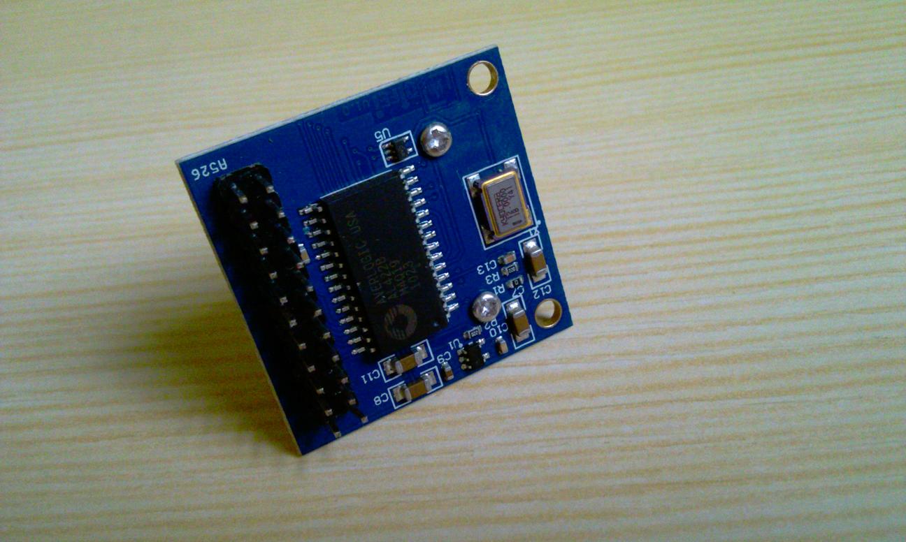
Overall, I wasn't exactly thrilled with the VC0706. If you add to that that I somehow managed to brick it, starting looking for a different solution was the right thing to do. It turned out that EBAY was filled with relatively cheap camera modules, however, they all required to sample the image in parallel at the speed of their clocks (typically a few MHz and faster). That was of course a problem if you had intended to run it all on an ATmega328P (the only MCU I had experience with at that time). One option was to use a buffer such as AL422B, as can be seen on the OV7670 camera, to grab the high speed image and than read it from the buffer at a reasonable speed. However, the AL422B is quite big, heavy, pricey and I couldn't find many alternatives. I also contemplated using an external SRAM to store the image, but in the end I decided to go the way of a different MCU with a reasonably big internal SRAM.

I narrowed my search for a camera to 2 megapixel modules (1600x1200 sensor resolution). Specifically to OV2640 and MT9D111. These two were generally sold with 2.54mm adapters for easy connection. My plan was to replicate this adapter (connector, regulators, etc.) on my tracker. In the end, I chose the MT9D111 module for its smaller connector and better documentation.

The microcontroller I picked to run my tracker was Atmel's SAM3S8B with 47 usable pins (64 total) and 64kB SRAM. Later, I found it was also equipped with Parallel Capture Mode, a hardware interface dedicated to CMOS digital image sensors. Running at 64MHz and being able to stream the data directly from the camera to SRAM using internal DMA, the MCU wasn't supposed to have any issues with the task. However, having zero idea on how to implement this microcontroller, I ordered an Arduino DUE to familiarize myself with both programming and hardware requirements. The DUE ran on SAM3X8E. Not exactly the same MCU, but similar enough.


Experimentation with the DUE and studying the SAM's datasheet slowly led to the actual board design. One thing I wasn't completely certain about was the programming interface. In the end I routed both the USB interface (the ideal option) and the UART0 pins as a backup (alternative serial programming) to a cuttable part of the board. Aside from those it was handy to route connections to the ERASE and RESET pins nicely next to 3.3V and GND respectively. That allowed me to use a simple jumper when I needed to erase the flash memory (ERASE pin -> 3.3V) or reset the MCU (RESET pin -> GND).
For anyone interested in a detailed examination, here are the EAGLE files:
TT7-F v1.4.sch and
TT7-F v1.4.brd
The board design took place during the last winter. About that time DL7AD introduced his PecanPico7 tracker which was attempting to accomplish the same task, an SSDV floater. It was interesting to see, how somebody else coped with it.
After a month of waiting, I finally received my boards from DirtyPCBs in mid March. Some more delays in parts delivery pushed the start of the actual assembly to the beginning of April. I chose 0.8mm thickness for the PCBs which led to weight of 2.01g per board.
Wanting to do the soldering myself this time, I had bought a fairly ordinary soldering iron with exchangeable tips and a hot air station for the QFN packages and the tiny bits (a lot of the resistors, capacitors and inductors were in 0402 packages). Since it was my first time soldering things like this, I spent some time practising on other boards I had at hand. This is the LNA from the previous post about antennas.
I started soldering section by section. The USB Micro-B connector was the only partially through hole part on the board. The rest was SMD.
Here is the complete power supply soldered up. The board can be powered either through the USB interface (a regulator steps the voltage down to 3.3V and the resistors protect the data lines) or through the buck-boost converter (TPS63031) that takes in 1.8-5.5V. Additionaly, there is an MPPC step-up converter (LTC3105) for charging the battery from solar cells.
Not everything went great the first time. I had to re-do the LTC3105 section.
Testing the power supply - the battery input.
TPS63031 - the operating voltage.
ME6211C28 - the regulator for the MT9D111 camera.
ME6211C18 - the second camera's regulator for its digital circuits.
And further testing with the LTC3105 re-soldered.
I even found purpose for the solar logger again. Measuring the current across a 1
Ω resistor provided to the battery port by the LTC3105 and a pair of 52x26mm solar cells.
With the power supply verified, I moved on to the Si4060. The QFN package required the hot air station again. To apply the soldering paste, I usually used the thicker part of a needle with a droplet of the paste and tapped the pads until it stuck to it. Additionaly, I used a wooden tooth-pick to remove excess paste or re-position it properly. No high-tech solutions.
Probably due to that, I ended up with a few shorts between the pins. Though those were easily repaired with a soldering iron and a little flux.
After that I used the hot air to solder the remaining parts - a few decoupling capacitors and the matching and filtering section.
I was a little uncertain about soldering the SAM3S8. A pricey part, a lot of pins... so I decided to practise on an old TT7-40 board and an ATmega328P I still had. I tried doing one side with the paste and hot air while the other side with a soldering iron, a chisel or round sloped tip, and a lot of flux. I definitely achieved better results and felt more confident with the soldering iron so I went with that.
I think I had to remove a few shorts but nothing of too much bother. I guess it's just a matter of practice than anything else.
To clean the boards from the residual flux I always used isopropyl alcohol.
And the SAM was alive! The lit LED confused me a little at first. Especially since the other remained dark. Later, I learned that most of the pins get pulled up after reset which was enough to light up the LED a little. The second LED was placed on a System I/O line which stays low at startup.
Soldering of the UBLOX module, I practised on the old rainswept TT7-40 tracker. Using the soldering iron and flux came out as the better option again. The tracker was tested to work with both MAX-7C and MAX-M8Q.
My initial plan was to always use the MT9D111's adapter for the regulators and the connector. However...
...that plan went quickly out of the window after a couple of clumsy taps with a hot soldering iron. That led to another delay since I had to wait for more then a month for a batch of the connectors to be delivered from Aliexpress (the connectors weren't at all easy to find - if anyone was ever looking for them, they were Kyocera 145602‐030000‐829).
The arrival of the connectors takes us to early May. This time, I was much more careful and practised on spare boards. The best way was to tape the connector down to the board and gently tap the ends of the pins with a soldering iron (and using a lot of flux again). Looking at it again, the layout of the pads could be better with the oposing sides closer together. The connector is not as wide as I thought based on the drawings in the datasheet.
And finally the whole board all soldered up. The leads to the battery terminals and solar panel terminals were just temporary for ease of use in testing. The flight ready tracker would have the battery and solar cells soldered straight to the terminals with much shorter leads.
The Si4060 antenna was a temporary solution as well. Just a piece of wire of a 1/4 wavelength (164mm for 434MHz, 492mm for 144.8MHz). For an actual flight, I would use the ground pads and vias to create a proper ground plane antenna. The Ublox antenna on the other hand was a permanent solution. Placed outside, the module had no problem aquiring lock with just a 1/4 wavelength piece of wire in place of its antenna (45mm).
At this point, I should address a couple of things that had to be corrected. I forgot to connect SAM3S8's ADVREF pin to 3.3V so the ADC didn't have a reference (I was probably under the influence of ATmega328P which provided an internal reference to the operating voltage). On the actual board, I solved this by soldering a piece of wire from the pin (which is conveniently located at the corner) to the main 10uF input capacitor nearby.
Second issue came up when I attempted to communicate with the camera via its TWI interface. The datasheet asked for 1.5k
Ω pull up resistors on the SDA and SCL lines, however, this didn't bring any successs so after a bit of experimentation I settled on 6.8kΩ pull ups that worked fine.
This is a close-up of the programming interface. The SAM3S8 has to have an external crystal or clock on XIN and XOUT pins with frequency of 11.289MHz, 12MHz, 16MHz or 18.432MHz. The DDM and DDP pins connected to the USB's D- and D+ terminals across a pair of 27
Ω resistors and that is it.
To program the MCU you erase the internal flash memory by momentarily connecting the ERASE pin to 3.3V.
Then you reset the MCU by shorting the RESET pin to GND.
And after Windows install the necessary drivers and identify the USB device you can connect to the MCU via Atmel's SAM-BA. Then simply choose the compiled .BIN file of your script and send it to the device. After successful upload, you execute the 'Boot from Flash (GPNVM1)' command, reset the MCU again and the tracker should be running your program.
With that sorted, I started probing all the individual devices to verify they work. Here's the Ublox outputting the standard NMEA messages. One thing to take into account in your program if you have some of the trackers equipped with MAX-7C and the others with MAX-M8Q. The older chip initially outputs messages named GPGGA, GPRMC, etc. while the newer one (having GLONASS functionality) initially outputs GNGGA, GNRMC, etc. so the parsers have to be able to tackle that. The same goes for NMEA message requests. MAX-7 will expect 'GP' while MAX-8 'GN' commands.
The camera gave me much more trouble making it work and so required a more permanent probe. The tracker itself didn't provide easy access to the MT9D111 pins which proved challenging when trying to find out what was wrong with it.
It made me return to the original adapter and Arduino DUE to write all the functions and verify the issue wasn't in software. In the image above there are the main pins used in communication between the MCU and the camera. After the MCU provides 6MHz (or higher) clock to the camera on its CLK pin, SDA and SCL lines are used to read/write registers and variables in the camera. The camera then continuously outputs signals on VSYNC (active frame), HREF (active row), PCLK (clock to which the output is synchronized) and D7 to D0 pins (8 bits of the image per one PCLK clock cycle) according the its settings.
My issue, however, was that I couldn't command the camera to change its output which was necessary, because in default the camera output 800x600 YCbCr images that simply woudn't fit inside the SAM's 64kB SRAM. The search for the origin of the issue drove me as far as replacing the ME6211's capacitors for higher values and even considering pulling the TWI lines up to 3.3V instead of the ME6211's 2.8V to, in my mind, ease of the camera's supply. That stuck I was with it.
After almost giving up on the idea that my tracker would ever be SSDV capable, I finally cracked it last week when I re-examined the TWI communication between the camera and the MCU. It turned out that while register writes and reads, 16-bit variable writes and reads, and 8-bit reads worked fine, 8-bit writes did not. An issue I thought I had checked and an issue unnoticeable on the DUE, because of the use of its Wire library instead of my own functions. The thing was that most of the 'change state' commands were those 8-bit variable writes. So the end result was giving the impression that the camera could do reset, could write registers and variables and read them back, but couldn't refresh the output.
That breakthrough finally allowed me to verify that SAM3S8 was capable of capturing the smaller uncompressed and compressed JPEG images, and play a little with image quality in different light conditions. These are 144x112 RGB565 images occupying 32.256kB per image in the MCU memory.
These are 320x240 JPEG images with the quality factor of 69. The images range from 12kB to 20kB.
These are 480x352 JPEG images. Quality 50. Size 20-28kB.
640x480 JPEG images. Quality 25. Size 16-26kB. The number of artifacts in the image increases.
Just for an example a 800x600 JPEG, quality 25, size 25.5kB.
And 1024x768 JPEG, quality 20, size 31.5kB.
It is necessary to say that these are the nicer images I could get from the camera. It was not that hard to end up with a pretty bad image. Some more experimentation with the register settings may be required in the future to get better output. However, for now I intend to use the smaller 320x240 images with higher quality for SSDV. The SSDV process will further decrease the image quality a little bit as well as its size.
The finished tracker without a battery and with a simple wire antenna weighed 4.58g.
With the MT9D111 module the weight increased to 6.03g.
That was the hardware side of the TT7F tracker. In the future, I intend to write a few words on the software side as well. And if everything goes well, I could do its first launch somewhere during this month.


