So far, I have been soldering all my tracker boards and other PCBs by hand with either a soldering iron or a hot air station. This often led to repeatedly reheating the same boards and ICs as I usually did them in parts. That most likely wasn't an ideal practice as some of the solder joints liquefied and solidified again and again at uncontrolled conditions. I suspect it could have contributed to some of the tracker failures I have experienced. Having that in mind, I began coming across videos and tutorials on people modifying ordinary toaster ovens to homemade reflow soldering equipment. Here is just one
example from which I've sourced a lot of useful information. A Google or a Youtube search will bring up many more. Eventually, I began putting together my own reflow oven and this blog post now documents the process.
Armed with recommendations from the mentioned tutorials, I looked for the smallest cheapest oven equipped with quartz heating elements as these should have been better suited for rapid temperature changes. My choice fell on Tristar OV-1431 which was advertised as a 9 liter 800W toaster oven. The inner dimensions were 250 by 215 with 162 millimeters in height.
Inside the chassis was a heating chamber with two quartz heating elements. One at the top and one at the bottom. Then on the right side was a separate space housing the control mechanism which was going to be replaced.
At the back side of the oven, only a thin metal plate separated the heating chamber from the outside environment leaving no space for any additional inner insulation. The whole bottom metal plate of the oven then could be opened (probably for cleaning if used in its intended purpose). In any case, it led to openings along the whole circumference for heat to escape.


These are a couple of images from the first time I turned the unmodified oven on. As can be seen, the heating elements operate at high enough temperature to partially radiate in the visible portion of the electromagnetic spectrum. The oven's documentation, perhaps unsurprisingly, doesn't say anything about the type or properties of the heating elements. Upon a closer look they consist of a thin coiled wire which as a result operates at higher temperatures than the thick metal elements found in other types of ovens. The coil itself is housed in a quartz glass tube which is predominantly transparent to the emitted infrared radiation.


The original grid was replaced with a solid aluminium plate to distribute the heat under a PCB more evenly. I recall seeing stripes burned onto a board were it was touching the grid from one of the tutorials I've seen. Ideally, the plate should be able to provide sufficient support while being as thin as possible so it doesn't take too much time to heat itself. The dimensions I managed to obtain were 256 by 210 millimeters in 1mm thickness. Although judging on its strength, it could have been thinner.
Having familiarized myself with the oven, I wanted to get an idea of what it could do. I used a thermocouple and an Arduino to log the temperature readings during three different runs. First I left the thermocouple hover in mid air inside the heating chamber without the aluminium plate. On the second run, the thermocouple was taped to the plate with a Kapton tape. And lastly, I pushed the thermocouple through one of the side vents to see how hot it got inside the side space.

These were the results. In all three cases, I set the oven to full power, left it running until the temperature stabilized, and let it cool down with the glass door closed. The oven's highest setting was 230°C. As evidenced by the second measurement (red), that indeed was where the inside temperature stabilized after an initial overshoot before the built-in thermostat intervened. The first measurement (blue), where the thermocouple hovered in mid air, was probably influenced by direct absorption of the radiated heat by the thermocouple probe as the temperature first overshot to about 285°C then stabilized at only about 205°C with the heating element's duty cycle now much lower. Lastly, the air temperature in the shielded side space reached an uncomfortable 82°C.
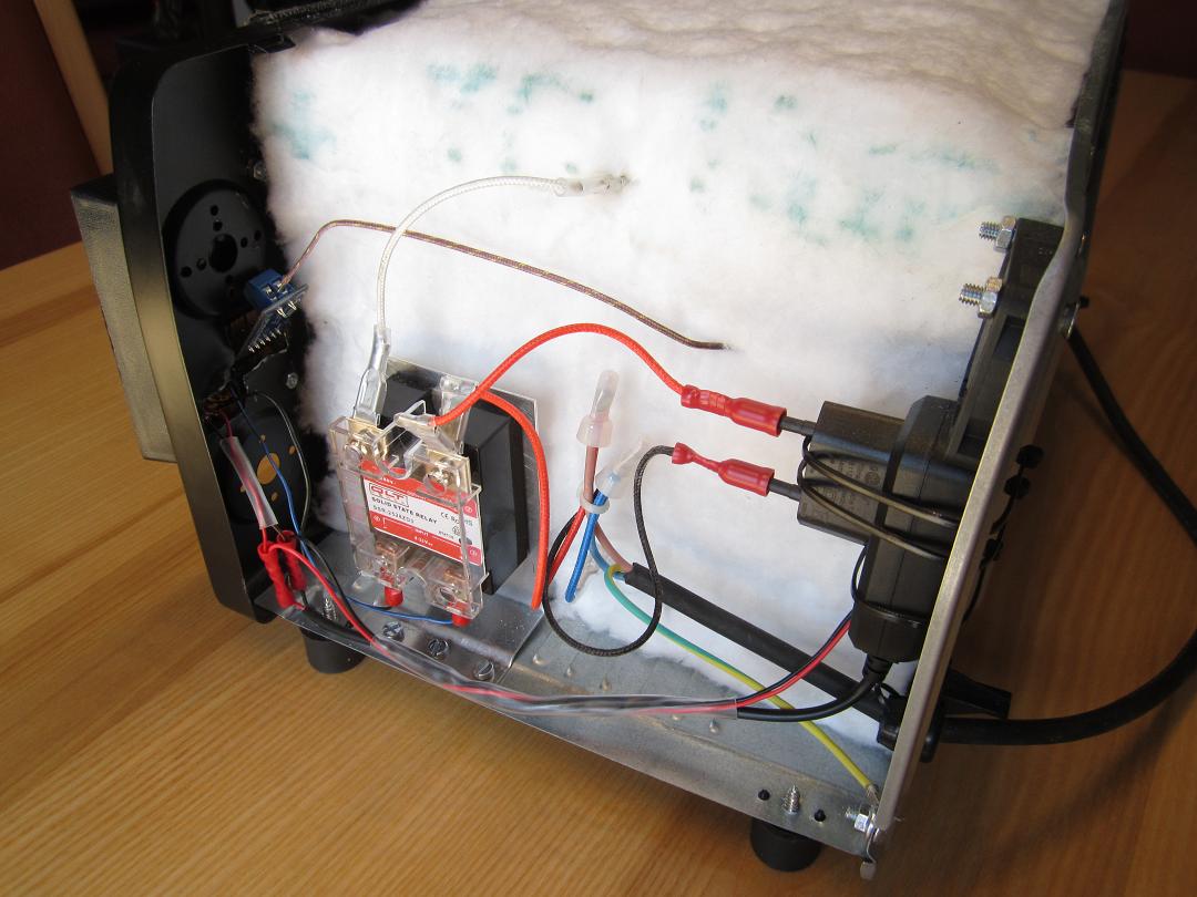
After that, it was time to take off the main cover and examine the inner wiring. A good sign was that there seemed to be enough space for additional insulation to go in between the cover and three sides of the heating chamber.


Since this was a very basic oven, the control mechanism constituted of only a timer (bottom) and a thermostat (top). As for the wiring, the protective earth (green/yellow) from the power cord was screwed down to the oven's chassis. Contrary to convention, 230V was measured between the blue wire and the earth connection while the brown wire was at 0V to earth. Thus the live wire first fed the bottom heating element, then connected the two elements in series on the other side of the oven, and returned through the upper element to the thermostat's terminal. From the thermostat's second terminal, it continued to one of the timer's terminals, and finally returned to the brown (neutral in this oven) power cord wire via a second terminal. Both the timer and the thermostat worked as two circuit breakers in series.


A control light, signalling the oven's operation, was wired to the mains line as well. It was fed via a black wire crimped to the power cord's blue wire and completed the circuit via another black wire to the timer's live terminal.
A closer look at the heating chamber revealed a number of gaps and holes in the bottom panel and in between all the walls. Sealing them and further insulating the chamber would result in less power wasted on heating the outside environment and it would speed up the temperature growth inside the oven as well.
Having an idea of what others have used in the task, I ordered a high temperature (1200°C) stove sealant, a fiberglass blanket (1050°C), an aluminium reflective tape (350°C), and an adhesive gasket (600°C) for the glass door. All of this can be found in shops specialized in building/selling stoves, garden grills and their accessories.
As mentioned, there was quite a lot of holes and gaps all around the heating chamber. These were first all filled with the high temperature stove sealant. Since the gaps were generally quite wide and hence the layer of the sealant quite thick, it was left to harden for about 4 days. Maneuvering with the sealant tube inside the chamber was problematic, so the seams were done mainly from outside.
To limit the amount of heat escaping through the glass door, most of it but a small window was taped over with the aluminium tape. The reflective surface decreases heat absorption by the glass and transmission through to the outside environment.
Unfortunately, there were visible gaps all around the glass door as well.
It took a while to find the best arrangement for the adhesive gasket so it didn't leave any chinks anywhere, but eventually the door seemed better insulated.
Majority of the insulation was conveyed by the fiberglass blanket. The 13mm thickness just fitted into the main cover. It was wrapped around the chamber from three sides in one piece. The heating element's terminals were simply pierced through the blanket without any hassle.
With the insulation done, I repeated the same temperature measurements and added a couple more. The oven and its surroundings were noticeably cooler than when it ran in its original condition.
The first chart compares the situation with the thermocouple in mid air. This time the oven was manually switched off when the readings reached 300°C, because the thermostat, due to the insulation, no longer responded properly. As can be seen, the temperature rise was sharper, and the previous maximum was reached two minutes earlier. The second chart shows how the temperature progression changed when the aluminium plate was put in and separated the thermocouple from direct radiation of the bottom element. Contrary to the previous situation, the door was fully opened right after the readings hit 300°C. The much delayed peak suggests that the thermocouple in this configuration is largely influenced by direct absorption, and the readings don't necessarily reflect the air temperature.

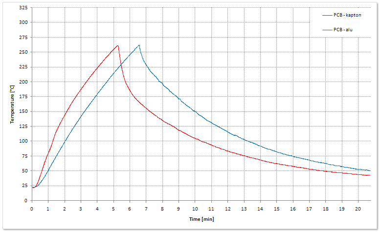
In this case, the first chart compares the situation with the thermocouple taped to the plate with Kapton tape. This time the power was shut and door opened when the readings hit 260°C. Again, the rate of temperature increase was higher. The second chart compares the same situation to one where a piece of the reflective aluminium tape was used to secure the thermocouple. The results suggest that using Kapton tape, the thermocouple still absorbed some radiation directly and skewed the temperature readings.
Since the side space was intended to house the replacement electronics, and its 80°C operating temperature in the original oven was at the limits of some of the components, the situation after insulating the oven was of significant interest. This time the power was cut when the temperature readings stabilized. As can be seen, the maximum air temperature decreased by some twenty degrees and the peak was hit after about seven minutes.
Out of interest, I did a couple of measurements with the thermocouple taped to a ground pad on a 1.6mm PCB. Again, Kapton tape and aluminium tape were used in separate runs. The board was placed in the middle of the plate.
Unsurprisingly, the Kapton tape readings showed a higher temperature increase rate. The second chart then compares the situation when the thermocouple was taped to the aluminium plate to the run with the PCB measurement. Even though the plate was physically much larger, the resulting curves are very similar and differ only by less then a 30 second delay.
Since the aluminium tape covering the door had survived several runs without any signs of peeling, it was used to further limit absorption by the chamber's walls. Although it was kept some distance away from the heating elements. A couple of the reflow oven tutorials mentioned similar tapes catching fire when placed too close.
To further decrease the operating temperature in the side space, a small 5V fan was attached to the air vents in the rear wall of the oven. The chart then shows a comparison of the measured temperature profiles with and without the fan. Contrary to the first two measurements, in this instance, the power to the heating elements was cut after 5 minutes. The fan seemed to decrease the air temperature by further 10°C. Note that this profile was taken while the fan was partially obstructed by the air vents themselves. In the final layout, the air vents were removed.

With a little bit of force, the control knobs could be taken off uncovering access to a few screws which then allowed dismounting the timer (in the image on the left) and the thermostat (right) completely. Both of them used 6.3mm flat terminals with a lock, so the wires could be taken off easily as well. The timer was a simple mechanical switch which used a spring and a set of gears to delay breaking of the circuit after it was wound up. The thermostat, as I understood it, used two metals of different coefficient of thermal expansion in its construction. The more expansive piece of metal detached from its less expansive counterpart breaking the circuit when it reached target temperature. Judging by the arrangement of the thermostat in the oven, it responded to the heat delivered to it by conduction in the front panel and temperature of the air in the side space. This relationship was broken by the added insulation.
These are a few photos from preparations of the side space for the replacement controls. As luck would have it, the connections to and between the thermostat and
the timer meant that I would only have to replace two connectors on the
existing wires (high temperature resistant) and could use them in the new
setup. A large air vent for the fan and a few holes for a 5V power supply were drilled in the back wall. Mounts and openings for a controller in the front panel, and holes in the floor for a solid state relay as well. Missing from these images is one more hole in the side wall of the heating chamber for the thermocouple probe.

This is a schematic of the mains circuitry that replaced the original one. The mains electricity in the Czech Republic is 230V at 50Hz AC. The resistance of the upper heating element was measured to be 37Ω while the bottom element showed 29Ω. The elements are wired in series which means the current passing through the circuit is 3.5A. A 25A zero crossing solid state relay (SSR) operated by a low voltage controller switches the mains branch with the elements on and off. A parallel mains branch feeds a 5V DC power supply unit which provides power to the controller and the fan. The protective earth wire is screwed down to the oven's chassis.
A 120 by 55 millimeter aluminium plate 1mm in thickness was bent a few times to form a mount for the SSR. The relay was smeared with a thermally conductive paste in the area of contact. Contrary to the label, the DC input voltage limits of the SSR are 3-32V according to the datasheet allowing a 3.3V Arduino ProMini to control it.
As mentioned, the mains wiring was done with the original cables and a couple new round terminals for the 5V power supply unit. The low voltage wiring used fork terminal and butt splice connectors all secured with a crimping tool.
Usage of these wall pluggable power supply units to provide power to the low voltage circuits in the other reflow oven build guides seemed like a simple and elegant solution to me, so I followed the same approach. The choice fell on a 5V 1A model which would easily power the controller and the fan.
This is a schematic of the low voltage controller. It was built around a 3.3V Arduino ProMini and it is powered by the 5V unit via the RAW pin. The microcontroller interfaces with a MAX31855 module (SPI), an OLED display (I
2C), and the SSR (pin D7). Two buttons allow changing settings and starting or halting the reflow process. An LED and a buzzer provide visual and audible notifications. The controller, just like the fan, starts operating the moment the oven's power cord is plugged in the wall power supply.
The MAX31855 is a thermocouple-to-digital converter with an inbuilt cold junction compensation. In terms of the oven, the module and hence the cold junction are placed in the side space while the thermocouple probe measures inside the heating chamber. Both temperatures are displayed on the OLED screen. This specific module is intended for K-type thermocouples. The wire provided with the module can measure between -73°C and 482°C.
The layout and wiring of the finished controller can be seen in the images above. The exposed Arduino allows connecting to a PC and can be easily reprogrammed. The box itself fits onto the oven's front panel.
These images document the final arrangement of the individual parts. The 5V power supply unit was secured to the back wall with the help of a few cable ties. The fan, the SSR and the controller were all screwed down in place.
The thermocouple probe was anchored in place with the high temperature sealant from the inside of the heating chamber. And finally, the uninsulated 6.3mm terminals were covered with a see-through heat-shrink tubing.
This is what the finished oven looks like with the main cover back on.
And a couple of detailed shots of the controller in the front and the fan in the back.
The goal of the modifications was to help the oven to replicate a temperature profile required to safely reflow SMD components on a PCB. These profiles, or at least some of the limits, can be found in datasheets of individual parts and specifications of soldering pastes. The ones I came across usually referenced IPC/JEDEC J-STD-020E as the standard they complied with. The chart above shows the minimum and maximum profile length and shape that follow the specification. My intention was to make the oven perform somewhere between the two boundaries. As is apparent from the peak temperature, this is a profile for a lead based soldering paste (Sn63 Pb37) with a lower melting temperature (183°C) than it is in case of the lead-free pastes (217°C with peak profile temperatures around 250°C).


To help with developing the oven's controller, the Arduino was connected to an SPP-C Bluetooth module which periodically transmitted tracked data. The current time as measured by the Arduino, the thermocouple temperature, the cold-junction temperature, the deviation of the thermocouple temperature to the desired temperature, the proportional, integral and derivative components of a PID controller, and so on. Some of the information was accessible through the OLED display as well.
The code I came up with was based around a 25ms interrupt routine running in the background. The SSR required crossing a zero voltage level to switch its state which with a 50Hz power supply put a limit of 10ms on how quickly it could break or close the heating element circuit. When the red button was pressed, the Arduino started regular 250ms cycles (every tenth interrupt) at the start of which it measured the thermocouple temperature and decided on a duty cycle for the remainder of the 250ms period. Since the interrupt was set to fire every 25ms, the duty cycle could be chosen in 10% increments.


First of all, I carried out fixed duty cycle measurements to get an idea of what the oven could do. The solid lines represent situations where the thermocouple was freely hovering above the aluminium plate. While taping the probe to the plate (alu tape) is documented by the respective dashed lines. I also tried shielding the tip of the thermocouple with a roll of the aluminium tape, but it had little impact on the measurements.
As the first attempt to control the temperature profile, I wrote a simple PID algorithm. A very nice explanation of a basic PID code can be found at this
link. In practice, it meant that the interrupt routine wouldn't assign a fixed duty cycle in the regular 250ms cycles, but would rather compute the proportional, integral and derivative portions based on a setpoint temperature, multiply them with respective terms (Kp, Ki, Kd), and arrive at the desired duty cycle in this way. The chart above illustrates one specific setting of the terms (Kp=0.5, Ki=0.05, Kd=0.0) in two configurations. First, with the thermocouple in free air and second, coupled to the aluminium plate. From the data and further attempts, it became apparent that the oven wasn't powerful enough to allow the controller to do too much, and that there was possibly a simpler approach to reproducing the desired profile.

Seeing that to approach the desired temperature progression, the oven had to often work at 100% duty cycle, I came up with a simpler method which divided the process into several zones with their own duty cycles. The chart above illustrates one specific zone/duty cycle setting with the thermocouple in free air, taped to the plate, and taped to a small PCB which was supported in corners by four other PCBs to avoid touching the plate directly. Upon pressing the start button, the oven entered a Warm-up zone where it ran at 100% duty cycle until it reached 50°C. Then switched to a Preheating zone and continued at 100% duty cycle to 150°C. A Soaking zone with 60% duty cycle followed all the way to 180°C. Then a Ramp-up zone at 100% duty cycle again, and finally, after reaching 225°C, a Reflow zone with 30% duty cycle lasting 15 seconds. After that the elements were shut down and the glass door was opened. All temperature levels and duty cycles can be easily changed in the code if needed.


As can be seen from the previous data, the process is strongly dependent on where the temperature is measured. The aluminium plate is quite thermally massive, and when a PCB is laid directly on it, it conducts heat away from the PCB. A possible way to limit this thermal coupling is using a less conductive material to support the PCB above the plate. As the images above document, I tried four smaller boards while minimizing the contact between them and the target PCB.
One of the tutorials also mentioned that in case of a joint control of the bottom and the top element, in other words lacking the ability to control the elements' duty cycles separately, the parts on top of the PCB could be overheating due to uneven direct absorption while the PCB itself is still approaching the target temperatures. To test this, I taped the thermocouple probe to an MCU on an old PCB as in the image above.


This chart is a comparison of different placing of the thermocouple probe. The measurements were all done with the oven running at 100% duty cycle. The naked probe free air situation (blue) is very similar to shielding the probe with a roll of the aluminium tape (purple) - also hovering in free air. The yellow and red curves show a significant difference between a smaller PCB (30x22x1.6mm) and a larger one (70x30x1.6mm) with uncovered ground plane, both supported in corners by four other boards. In case of the larger PCB, the temperature progression approached the one of the aluminium plate itself (brown). The temperature of an MCU (green) soldered to the larger PCB then suggests that, in deed, there was uneven heating between the board's ground plane and the component which settled at a 30°C difference.


To eliminate the impact of thermocouple placing, I eventually moved on to temperature independent time and duty cycle based control. The previously acquired data served as the basis for choosing the new settings. In the first case (chart on the left) once the temperature rises above 50°C, the oven runs at a 100% duty cycle for the next 70 seconds (Preheating), then reduces the duty cycle to 50% for another 100 seconds (Soaking), the next 60 second period heats up the chamber at a 100% duty cycle again (Ramp-up), and the peak lasts for 15 seconds at a 30% duty cycle. After that, the glass door is opened and the heating elements switched off (Cooling). In the second case (chart on the right), the Preheating phase is prolonged to 80 seconds and the Soaking phase to 150 seconds with its duty cycle increased to 60%. The charts then illustrate what impact this control has on the free air, small PCB (supported by other boards), large PCB (also supported), MCU and plate temperatures. In the second chart the measured MCU temperature peaked at 262°C which may be just above the absolute limit I've seen a number of microcontrollers to have in their datasheets.


Backed by the latest data, I finally did the first actual soldering test. A small 1.6mm thick board with a few components and loosely applied leaded paste was used. The paste was actually a year past its expiration date. Nevertheless, the shorter time based profile managed to reflow the components just fine as visible in the image above.
Following that, I did a final test to see whether the area of the plate was heated evenly. Five identical PCBs, this time 1mm in thickness, were distributed in the middle and in all four corners. Without a stencil the paste was smeared over the pads somewhat leisurely which could possibly explain why one of the resistors from the far left corner had reflown a little crooked. Otherwise, the result seemed satisfactory.
I imagine that ideal profile settings may vary a little depending on the actual PCB and components being reflown. Doing a couple of test before reflowing a new type of board may be a good idea.
Looking at the consumption, the controller (20mA at 5V) and the fan (185mA at 5V) run continuously when the oven is plugged in the mains supply, but represent the much smaller portion in comparison to the heating elements (3.47A at 230V). Factoring in the duty cycle of the shorter time based profile, the oven consumes 49.9Wh of electrical energy per one run.
| Tristar OV-1431 |
27.2 |
MAX31855 thermcpl. |
23.4 |
| Fiberglass Blanket |
7.4 |
SSR-2528ZD3 |
10.2 |
| Stove Sealant |
4.7 |
5V Power Supply |
4.3 |
| Aluminium Tape |
5.5 |
5V Fan |
2.6 |
| Gasket |
1.4 |
OLED Display |
2.3 |
| Aluminium Plate |
3.1 |
Arduino ProMini |
1.7 |
| Aluminium Mount |
0.4 |
Buzzer, LED, Resistors |
0.6 |
| Nuts, Screws |
2.0 |
Box w/ universal PCB |
2.3 |
| Thermal Paste |
1.1 |
Heat-Shrink Tubing |
1.5 |
| Shipping |
10.5 |
Crimp Connectors |
3.8 |
|
|
Total |
€116.0 |
Finally, the bill of components and materials is summarized in the table above (all costs are in Euros). Almost everything was sourced locally in the Czech Republic. Only the OLED display and the Arduino were ordered on Ebay.
The Arduino script running the oven can be found on github:
ProMini_Reflow_Oven.ino