This article will zoom in on programming the SAM3S8B microcontroller that runs TT7F. There are currently two Github repositories with code for the tracker. The first one
TT7F-UpDw-Tracker is the complete code used on the first launch of TT7F in the Up-and-Down setup. The second one
TT7F-Float-Tracker is the main repository and work in progress that currently contains all the libraries, however, so far not any final routine.
Coming from Arduino and AVR environment which is very rich in resources, I had trouble finding out how to even start with somewhat more advanced ARM processor at first. The hardware side of programming TT7F was pointed out in
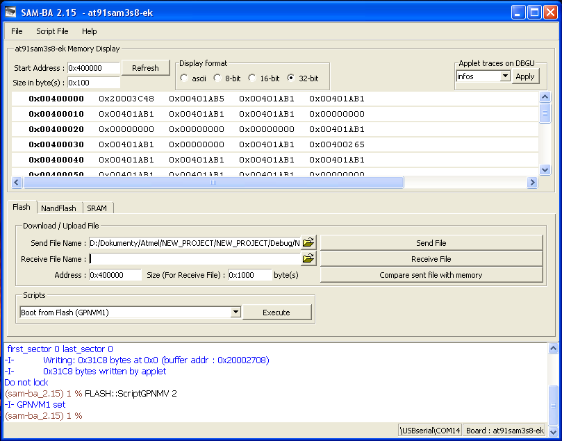
The TT7F Hardware so I will start at the moment the erased and reset microcontroller connects to a USB port. From the start I have been using Atmel's SAM-BA software.
After selecting the proper port and board the software connects to the MCU and provides a view of the state of the internal memories.
At address 0x00400000 we can see the start of the erased internal flash memory that will eventually host our code compiled to individual instructions. The SAM3S8B has one 512KB plane of flash memory that apart from holding the code can be used to store data.
To do the coding, I chose Atmel Studio 6.2. After creating a 'New Project' and selecting the desired device 'ATSAM3S8B', it opens an almost empty script. The
#include "sam.h" line contains a series of #defines and #includes that search for the specific device within the whole SAM family and appropriate files to include in the project that hold a number of structures, enumerations and define directives to simplify the coding. The other pre-included thing in the project is the
SystemInit(); line in the main function. This routine sets the number of wait cycles for reading instructions from the flash, initializes and switches the mcu to run with the main oscillator, and finally initializes the PLL and switches the mcu to the maximum 64MHz frequency. After this the custom code may follow.
Atmel Studio also includes a number of example projects that came handy when I was finding out how to make individual peripherals work.
WatchDog ARM_WATCHDOG.c
One thing to do straight away in the script, unless you already know that you want to implement it, is to disable WatchDog which is enabled by default. Otherwise it means that the mcu resets every 8 seconds or so.
1
2
3
4
| int main(void)
{
SystemInit();
WDT->WDT_MR = WDT_MR_WDDIS; // disable WatchDog (enabled by default)
|
This can be done by writing the WDT_MR_WDDIS bit in the WDT_MR register as shown above. The line 4 also demonstrates general way of accessing registers in the code.
#define RTT        (0x400E1430U) /**< \brief (RTT       ) Base Address */
#define WDT        (0x400E1450U) /**< \brief (WDT       ) Base Address */
#define RTC        (0x400E1460U) /**< \brief (RTC       ) Base Address */
The
WDT bit represents a specific base address in the memory for all the registers of one peripheral.
typedef struct {
  WoReg WDT_CR; /**< \brief (Wdt Offset: 0x00) Control Register */
  RwReg WDT_MR; /**< \brief (Wdt Offset: 0x04) Mode Register */
  RoReg WDT_SR; /**< \brief (Wdt Offset: 0x08) Status Register */
} Wdt;
The
WDT_MR part then represents an offset of the specific register from the base address.
#define WDT_MR_WDDIS (0x1u << 15) /**< \brief (WDT_MR) Watchdog Disable */
And finally
WDT_MR_WDDIS refers to the desired bit operation. In this case writing the bit 15 to '1' and all the other bits in the register to '0'. All this information is nicely shown by Atmel Studio upon right clicking the part of interest and choosing 'Goto Implementation'.
WatchDog is a safety feature that resets the mcu after a specific time. This is avoided by including commands to reset the WatchDog counter at specific places in the script. In case the execution of the code hangs at some point the counter runs out and resets the mcu. If the execution goes according to the plan the WatchDog reset command stops it from resetting the mcu and starts another round of timing.
The WDT_MR register can be written only once after mcu reset so the decision to use WatchDog or not is permanent. The 12-bit counter runs on the 32.768kHz Slow Clock divided by 128 allowing up to 16s WatchDog period.
Delay ARM_DELAY.c
Another useful thing is to set up a routine to manage delays when needed. The MCU offers the 24-bit SysTick timer for this purpose.
#define SYSTICK_LOAD 12000 // 64000 - 64MHz; 12000 - 12MHz; ...
Depending on the configured processor speed SYSTICK_LOAD in ARM_DELAY.h has to be adjusted. The timer is then used to fire an interrupt every 1ms that increments the 'timestamp' variable which determines whether it is time to exit the
SysTick_delay_ms() function. The timer has to be initialized by SysTick_delay_init().
LED ARM_LED.c
The TT7F board has two LEDs. After power up or reset most of the microcontroller pins (general purpose I/O lines - PAx pins) are by default pulled up to the operating voltage (3.3V) and controlled by the Parallel Input/Output Controller (PIO) with the output disabled. The pull up makes one of the LEDs slightly glow without configuring the PIO. The other one doesn't glow because it is located on a System I/O Line (PB5) that by default has the pull up disabled.
PMC->PMC_PCER0 |= (1 << ID_PIOA); // enable clock to the peripheral
Generally, it is necessary to enable the clock to a specific peripheral first before it can be used. Although, there are exceptions such as the RTT, RTC, etc. peripherals that are continuously supplied with clock signal and writing to the PMC_PCER0/1 registers is not required.
1
2
3
4
5
6
7
8
| void LED_PB5_init(void)
{
MATRIX->CCFG_SYSIO |= (1 << 5); // System I/O lines must be configured here as well
PMC->PMC_PCER0 |= (1 << ID_PIOB); // enable clock to the peripheral
PIOB->PIO_OER |= PIO_PB5; // enable Output on PB5
PIOB->PIO_PER |= (1 << 5); // enable PIOC control (disable peripheral control)
PIOB->PIO_PUDR |= (1 << 5); // disable pull-up
}
|
As opposed to the LED on PA0, controlling the PB5 requires assigning the System I/O Line to the PIOB controller by writing to MATRIX->CCFG_SYSIO register as can be seen on the line 3.
The LED library contains a couple of functions to either toggle the LEDs or turn them on for x milliseconds.
ADC ARM_ADC.c
TT7F uses three ADC channels to sample voltage on the solar panels (AD3), voltage on the battery (AD9) and the internal temperature sensor (AD15). Compared to the initial ADC script I used in TT7F-UpDw-Tracker I managed to improve on the volatility of the measurements.
ADC->ADC_MR |= (0x01 << 28) | (0x18 << 24) | (0x05 << 16) | (0x05 << 8);
Firstly by properly setting up the ADC_MR register in ADC_start() that should now have the TRACKTIM and TRANSFER timings according to the ADC's Electrical Characteristic bit in the datasheet.
 1
 2
 3
 4
 5
 6
 7
 8
 9
10
| for(uint32_t i = 0; i < n_averaged; i++)
{
ADC->ADC_CR = ADC_CR_START; // begin AD conversion
while(!(ADC->ADC_ISR & (0x01 << channel))); // End of Conversion x
ADCdata += ADC->ADC_CDR[channel]; // read the value
}
ADC->ADC_CHDR = (1 << channel); // channel disable
ADCdata = ADCdata / n_averaged; // finish the computation of the average
|
Secondly by sampling a number of times (usually about 100) and averaging the result within the ADC_sample() function.
This is an example of sampling the internal temperature sensor with 100 averaging for 10 minutes. Since the ADC output is a raw number between 0 and 4095, to get the final value in °C it has to be multiplied by 0.30402 and 274.887 has to be subtracted from the result. The actual calculation adds an offset (
TEMP_OFFSET) to the final result that can be found in ARM_ADC.h. For this offset every ADC has to be compensated individually.
ADC_start();
uint16_t AD3data = ADC_sample(3, 100);
uint16_t AD9data = ADC_sample(9, 100);
uint16_t AD15data = ADC_sample_temperature(100);
ADC_stop();
This is an example of the complete routine as I do it on TT7F.
UART ARM_UART.c
The UART interface is used to communicate with the Ublox module. Specifically the UART1. The UART0 pins are then routed to the side panel of the PCB as a backup programming interface. The Ublox receives and transmits at 9600 baud and this speed has to be matched on the mcu side as well. Specifically in ARM_UART.h the
UART1_BAUD define directive that represents a master clock divisor. As such its value to achieve 9600Hz is dependent on the master clock speed (64MHz by default, however, the mcu offers a wide range of possible frequencies at which it can run) and must reflect that.
PIOB->PIO_PDR |= PIO_PB2;  // disable PIO control on RX line
PIOB->PIO_PDR |= PIO_PB3;  // disable PIO control on TX line
PIOB->PIO_ABCDSR[0] &= ~(1 << 2); // select Peripheral A function on PB2
PIOB->PIO_ABCDSR[1] &= ~(1 << 2); // select Peripheral A function on PB2
PIOB->PIO_ABCDSR[0] &= ~(1 << 3); // select Peripheral A function on PB3
PIOB->PIO_ABCDSR[1] &= ~(1 << 3); // select Peripheral A function on PB3
Unlike in the LED example, the UART1 interface is located in the '
Peripheral A' domain and the pins have to be switched from PIO control to Peripheral A. This is done by disabling the PIO control in PIO_PDR register and selecting the desired Peripheral in the PIO_ABCDSR[0] and PIO_ABCDSR[1] registers.
UART1->UART_IER |= UART_IER_RXRDY;  // enable RXRDY interrupt
NVIC_EnableIRQ(UART1_IRQn);
While transmitting on the UART lines is done manually byte by byte. Receiving, due to its nature, utilizes an RX interrupt routine. Interrupts in general have to be enabled both in the specific peripheral and the Nested Vectored Interrupt Controller (NVIC) as seen above. In some case (other peripherals) it is necessary to enable the interrupt in NVIC first and then set up the peripheral's registers.
The RXRDY interrupt fires when a complete character is received and the result can be read in the UART_RHR register.
 1
 2
 3
 4
 5
 6
 7
 8
 9
10
| void UART1_Handler(void)
{
if(UART1_buffer_pointer < UART1_BUFFER_SIZE)
{
UART1_RX_buffer[UART1_buffer_pointer] = UART1->UART_RHR;
UART1_buffer_pointer++;
}else{
UART1_temp = UART1->UART_RHR;
}
}
|
When an interrupt fires, the processor enters the proper Handler (UART1_Handler() in this case). Given its specific use, I opted for a simple solution and set up a large enough buffer to hold any one sentence the Ublox module may send. This buffer is then automatically filled byte by byte as they are received and in the end should hold a complete sentence ready to be processed. After that the buffer is cleared and the
'UART1_buffer_pointer' reset to '0'.
UBLOX ARM_UBLOX.c
This library contains a variety of functions ranging from UBX and NMEA parsers, RTTY telemetry constructors to ASCII converter routines. After reset the Ublox module, by default, periodically outputs a number of standard NMEA sentences. At the same time it is open to receive commands consistent with the UBX protocol.
static uint8_t request0107[8] = {0xB5, 0x62, 0x01, 0x07, 0x00, 0x00, 0x08, 0x19};
static uint8_t requestGNGGA[15] = "$EIGNQ,GGA*39\r\n";
Using the UART1_TX() function repeatedly to send all the bytes within one of the arrays above equates to sending a command to the GPS module. In this case the module would respond by sending back one UBX-NAV-PVT message that contains numerous information about the module's position, current time, number of satellites, etc., or by sending back a GNGGA NMEA message that contains similar information. The main difference between the two protocols is that UBX communicates in binary values while NMEA in human readable ASCII format. That presents different challenges to the subsequent parsers.
static uint8_t setNMEAoff[28] = {0xB5, 0x62, 0x06, 0x00, 0x14, 0x00, 0x01, 0x00, 0x00, 0x00, 0xD0, 0x08, 0x00, 0x00, 0x80, 0x25, 0x00, 0x00, 0x07, 0x00, 0x01, 0x00, 0x00, 0x00, 0x00, 0x00, 0xA0, 0xA9};
static uint8_t setNAVmode[44] = {0xB5, 0x62, 0x06, 0x24, 0x24, 0x00, 0xFF, 0xFF, 0x06, 0x03, 0x00, 0x00, 0x00, 0x00, 0x10, 0x27, 0x00, 0x00, 0x05, 0x00, 0xFA, 0x00, 0xFA, 0x00, 0x64, 0x00, 0x2C, 0x01, 0x00, 0x3C, 0x00, 0x00, 0x00, 0x00, 0x00, 0x00, 0x00, 0x00, 0x00, 0x00, 0x00, 0x00, 0x52, 0xE8};
As mentioned above, the default settings result in periodic NMEA message updates. That is not very handy for simple parsing nor potential power saving. Generally, the first thing I do is to send 'setNMEAoff' command to the module to stop these periodic updates, followed by 'setNAVmode' command to set the module in
airborne mode. An important thing for high altitude ballooning. Otherwise the module stops outputting position data above approximately 12000 meters in altitude. Then I simply request the UBX or NMEA messages as I need them.
1
2
3
| UBLOX_send_message(request0107, 8);
UBLOX_fill_buffer_UBX(GPSbuffer, 100);
UBLOX_parse_0107(GPSbuffer);
|
This is an example sequence of commands. First it requests the UBX-NAV-PVT message from Ublox (line 1). Then it waits for the response by expecting a specific number of bytes to arrive in the
UART1_RX_buffer[] or it times out (line 2). If the expected number of bytes arrives, it copies them into 'GPSbuffer'. And finally it runs the respective parser (line 3). Within the parser routine it verifies that the received data actually represent the requested message, checks the checksum and parses individual data into respective global variables. The NMEA procedure is very similar.
$$$$TT7F1,1,20:31:15,49.49171,18.22271,1131,11,3,2048,4120,15, *0C5D\n
After having the current data prepared in appropriate variables, all that remains is running the
UBLOX_construct_telemetry_UBX() function. The result is a telemetry string such as the one above in the desired output buffer.
In telemetry construction, it is necessary to make sure any potential '0's right after decimal point are handled properly and the software doesn't omit them. This is predominantly a latitude/longitude issue. In my case, I use ASCII_8bit_transmit() for the integer part of the coordinate and
ASCII_32bit_LATLON_DECIMAL_transmit() for the decimal part. I make sure the '
figures' parameter matches the input's number of decimal places. For testing the parser and telemetry constructor, I wrote
UBX_Generator to have something for an input.
$GPGGA,092725.00,4717.11399,N,00833.91590,E,1,08,1.01,499.6,M,48.0,M,,*5B
One unpleasant difference between UBX and NMEA protocols is that the latter outputs latitude and longitude data in degrees and decimal minutes format (see above) while UBX provides nice and handy 32-bit integers representing decimal degrees such as
472852330 85652670 for the above coordinates.
All the different messages that the module outputs or can be used as commands are described in detail in the documentation provided by u-blox. Just google for:
'u-blox 8 Receiver Description Including Protocol Specification'. Another option is to install u-blox's software called
'u-center' and copy the messages from there. Generally, it can be used to connect to a u-blox module and send the commands from the GUI, however, TT7F board doesn't provide any simple way to connect just the module to a PC.
SPI ARM_SPI.c
The SPI interface is used to communicate with Si4060. Similarly to UART its speed is defined by a master clock divider (
SPI_SCBR in ARM_SPI.h) hence it's current processor frequency dependent. The Si4060's SPI interface can run at up to 10MHz which is useful for the more elaborate modulations (GFSK utilized in APRS requires quick communication). I used 8MHz (SPI_SCBR 8) when running of the 64MHz PLL and 6MHz (SPI_SCBR 2) with a 12MHz crystal oscillator.
 1
 2
 3
 4
 5
 6
 7
 8
 9
10
11
12
13
14
15
| uint16_t SPI_write(uint16_t data, uint8_t lastxfer)
{
...
if (lastxfer)
{
val = data;
SPI->SPI_CSR[0] &= ~(SPI_CSR_CSAAT);
}else{
val = data;
SPI->SPI_CSR[0] |= SPI_CSR_CSAAT;
}
...
}
|
The library contains a simple function SPI_write() that sends a byte of data and returns the byte received from the other device. The
'lastxfer' parameter is used to mark the last byte in a series of SPI_writes to de-assert the Chip Select line.
Si4060 ARM_SI4060.c
The transmitter's documentation describes numerous ways to construct packets with preamble, sync word, header, CRC checksum, etc. to transmit in the
'FIFO mode'. I haven't tested this method at all. All my implementations used the
'TX Direct mode' exclusively. In this mode, the data to be transmitted are fed to the device in real time through the GPIO1 pin. Thus all the timing and bit streaming is done by the TT7F's microcontroller.
1
2
3
4
5
| SPI_write(0x20, 0); // CMD: GET_INT_STATUS
SPI_write(0x00, 0); // PH_CLR_PEND
SPI_write(0x00, 0); // RESERVED0
SPI_write(0x00, 1); // CHIP_CLR_PEND
SI4060_CTS_check_and_read(9); // check clear-to-send (CTS)
|
After mandatory initialization of the Si4060 transmitter via
SI4060_init(
) which temporarily sets the SDN pin HIGH and runs the POWER_UP command, the device is ready. Above is a typical command structure. First byte is the command itself followed by a few arguments (in this case clearing interrupts). After the last byte and de-asserting SPI's Chip Select pin, check clear-to-send routine is entered.
 1
 2
 3
 4
 5
 6
 7
 8
 9
10
| while(dt != 0xFF && CTS_timeout)
{
CTS_timeout--;
SPI->SPI_CR = SPI_CR_SPIEN; // enable SPI if disabled
SPI_write(0x44, 0); // READ_CMD_BUFF
data = SPI_write(0x00, 0);
dt = (uint8_t)data;
if(dt == 0xFF) break;
SPI->SPI_CR = SPI_CR_SPIDIS; // workaround to de-assert chip select
}
|
The function repeatedly sends the READ_CMD_BUFF command until Si4060 responds with 0xFF signalling the command was executed and any potential data is ready to be clocked out.
The detailed API documentation is up for download at www.silabs.com as
'EZRadioPRO API Rev C2A-A2A'.
#define FREQUENCY_RTTY  434287000UL
#define TX_DEVIATION_RTTY 16
#define POWER_LEVEL  0x7F

#define COMPARE_VALUE_RTTY 2500
#define TIMER_CLOCK_RTTY 0x03

SI4060_init();
SI4060_setup_pins(0x02, 0x04, 0x02, 0x02, 0x00, 0x00);
SI4060_frequency_offset(0);
SI4060_frequency(FREQUENCY_RTTY);
SI4060_frequency_deviation(TX_DEVIATION_RTTY);
SI4060_power_level(POWER_LEVEL);
SI4060_modulation(2, 1);    // FSK, asynchronous
SI4060_change_state(0x07);    // TX state

TC0_init_RTTY_NORMAL();
SI4060_tx_RTTY_string_TC0("$$$$TT7F,2,tc0*A55D\n\0");
TC0_stop();

SI4060_deinit();
These are the typical steps to initiate a simple RTTY transmission. The code first sets all sorts of parameters such as selecting FSK modulation, the deviation of the two frequencies, the power of the output signal and commands the transmitter to begin transmission by entering 'TX state'. Right after that it configures TimerCounter0 to handle the timing of individual bits. The 'TIMER_CLOCK_RTTY' and 'COMPARE_VALUE_RTTY' define directives are responsible for transmission's baud rate. The former selects the clock utilized by the timer (in this case MCK/128) while the latter defines the number of clock periods until rising the
CPCS flag in the TC0 status register and reseting the counter (2500 resulting in 200 baud rate).
Example Implementation
Putting it all together, the main() function may look something like this.
 1
 2
 3
 4
 5
 6
 7
 8
 9
10
11
12
13
14
15
16
17
18
19
20
21
22
23
24
25
26
27
28
29
30
31
32
33
34
35
36
37
38
39
40
41
42
43
44
45
| int main(void)
{
SystemInit(); // initialize the Main CLK at 64MHz
WDT->WDT_MR = WDT_MR_WDDIS; // disable WatchDog
SysTick_delay_init(); // configure the delay timer
LED_PA0_disable();
LED_PB5_disable();
UART1_init(); // initialize communication to u-blox
SPI_init(); // initialize communication to Si4060
ADC_init(); // initialize ADC pins
UBLOX_request_UBX(setNMEAoff, 28, 10, UBLOX_parse_ACK);
UBLOX_request_UBX(setNAVmode, 44, 10, UBLOX_parse_ACK);
while(1)
{
telemCount++;
ADC_start();
AD3data = ADC_sample(3, 100);
AD9data = ADC_sample(9, 100);
AD15data = ADC_sample_temperature(100);
ADC_stop();
UBLOX_request_UBX(request0107, 8, 100, UBLOX_parse_0107);
UBLOX_construct_telemetry_UBX(TXbuffer, sequence);
SI4060_init();
SI4060_setup_pins(0x02, 0x04, 0x02, 0x02, 0x00, 0x00);
SI4060_frequency_offset(0);
SI4060_frequency(FREQUENCY_RTTY);
SI4060_frequency_deviation(TX_DEVIATION_RTTY);
SI4060_power_level(POWER_LEVEL);
SI4060_modulation(2, 1);
SI4060_change_state(0x07);
TC0_init_RTTY_NORMAL();
SI4060_tx_RTTY_string_TC0(TXbuffer);
TC0_stop();
SI4060_deinit();
}
}
|
After the opening initializations the script enters a while loop that repeatedly steps through data collection (ADC measurements, ublox requests), transmitter initialization, transmission and transmitter de-initialization. Then it starts another round.
#include "sam.h"
#include "ARM_ADC.h"
#include "ARM_DELAY.h"
#include "ARM_LED.h"
#include "ARM_SI4060.h"
#include "ARM_SPI.h"
#include "ARM_UART.h"
#include "ARM_UBLOX.h"
To make the basic code complete, it requires the involved libraries to be included at top of the script.
uint32_t sequence = 0;

uint16_t AD3data = 0;
uint16_t AD9data = 0;
uint16_t AD15data = 0;

volatile uint32_t SI4060_buffer[16];
volatile uint8_t TC_rtty_gfsk_lookup = 0;
volatile uint32_t TXdone_get_data = 1;
volatile uint8_t TXdata_ready = 0;
uint32_t TXmessageLEN = 0;
uint16_t APRS_packet_size = 0;
uint8_t TXbuffer[TX_BUFFER_SIZE];
uint8_t APRSpacket[APRS_BUFFER_SIZE];

volatile uint8_t UART0_RX_buffer[UART0_BUFFER_SIZE];
volatile uint8_t UART1_RX_buffer[UART1_BUFFER_SIZE];
volatile uint32_t UART0_buffer_pointer = 0;
volatile uint32_t UART1_buffer_pointer = 0;
volatile uint32_t UART0_temp = 0;
volatile uint32_t UART1_temp = 0;

uint8_t GPS_UBX_error_bitfield = 0b00100000;
uint16_t GPS_NMEA_latitude_int = 0;
uint32_t GPS_NMEA_latitude_dec = 0;
uint16_t GPS_NMEA_longitude_int = 0;
uint32_t GPS_NMEA_longitude_dec = 0;
uint8_t GPS_NMEA_NS = 1;
uint8_t GPS_NMEA_EW = 1;
int32_t GPS_UBX_latitude = 0;
int32_t GPS_UBX_longitude = 0;
float GPS_UBX_latitude_Float = 0.0;
float GPS_UBX_longitude_Float = 0.0;
int32_t GPSaltitude = 0;
uint8_t GPShour = 0;
uint8_t GPSminute = 0;
uint8_t GPSsecond = 0;
uint8_t GPSday = 0;
uint8_t GPSmonth = 0;
uint16_t GPSyear = 0;
uint8_t GPSsats = 0;
uint8_t GPSfix = 0;
uint8_t GPSnavigation = 0;
uint8_t GPSpowermode = 0;
uint8_t GPSpowersavemodestate = 0;
int32_t GPSgroundspeed = 0;
int32_t GPSheading = 0;
uint32_t telemCount = 0;
uint32_t telemetry_len = 0;
int32_t GPS_UBX_latitude_L = 0;
int32_t GPS_UBX_longitude_L = 0;
int32_t GPSaltitude_L = 0;
uint8_t GPS_NMEA_NS_L = 0;
uint8_t GPS_NMEA_EW_L = 0;
uint16_t GPS_NMEA_latitude_int_L = 0;
uint32_t GPS_NMEA_latitude_dec_L = 0;
uint16_t GPS_NMEA_longitude_int_L = 0;
uint32_t GPS_NMEA_longitude_dec_L = 0;
And a number of variables and arrays defined ahead of the main() function.
Clicking
'Build Solution' in Atmel Studio checks the script for errors and compiles it.
It also provides some useful information in the Output window such as how much flash memory the instructions will take up (Program Memory Usage) and what portion of SRAM is already used up at compile time (Data Memory Usage).
Returning to SAM-BA, all that needs to be done here is to insert path leading to the compiled
.bin file and click 'Send File'. After refreshing the memory display it now shows the flash filled with instructions from the 0x00400000 address onwards. Last thing to do is to 'Execute' the 'Boot from Flash (GPNVM1)' command and physically reset the microcontroller.
The result can be checked in an SDR software at the appropriate frequency (due to me using an uncalibrated RTL-SDR dongle here, the displayed frequency is off by about 60kHz).
And a successfully decoded telemetry string in dl-Fldigi.
This article hopefully outlined some of the basics in programming TT7F and SAM3S8 in general. A couple more specialized blog posts concerning software may appear in the future.