Monday 29 September 2014

The Transmitter

When I settled on the overall concept, I began searching for the specific parts. One condition was the availability of the parts for a reasonable price. Starting with the microcontroller, I chose Arduino Nano. Nano is one of the smaller models, but it still has a mini USB connector. That is useful for programming the microcontroller, because otherwise you need an additional board. I found it on Aukro (as mentioned before, the Czech version of Ebay).
When ordering the Arduino board, I went through the seller's other offers and came across a Ublox NEO-6M GPS module that would suit my purpose. Plus, I would save on the shipping costs. Additionally, by that time, I had already come across a couple of manuals dedicated to joining a Ublox module and an Arduino board. A significant aspect for me, since I saw both the Arduino and the GPS module for the first time in my life. An important thing when choosing the GPS module is finding a model that is capable of operating at high altitudes. Due to specific restrictions prohibiting commonly sold GPS devices to function at altitudes higher than 18km and at the same time exceeding the speed of 515m/s, this is not a norm. When programming such a module, you have to make sure that the 'airborne mode' or some version of the airborne mode is activated.
An existing manual played an important role in choosing the trnasmitter as well. I even managed to come across a Czech supplier. The transmitter in question was Radiometrix's NTX2 operating on 434.650 MHz.
The specific parts mentioned here are only those I actually used. Each one of them has more alternative options that would work just as well.
To interconnect all of this, I initially used a breadboard and a few wires. The wires can be easily obtained from a UTP cable and manually fitted with male or female connectors making it easy to connect and reconnect whatever you want.
Here, I was testing the wires using one of the basic Arduino educational scripts making the microcontroller blink an LED diode. The wires are fitted with KONPC-SPK pins and covered by an insulation.
This is the first wiring on a breadboard still using the USB as the power source. The Ublox module has 4 pins. The first labeled 'Vcc' connects to the Arduino pin '5V'. The second 'RX' goes to the Arduino's pin 'D4', the third 'TX' to the Arduino's 'D3' and the last 'GND' connects to the Arduino's 'GND'. The NTX2 has 7 pins. Three gathered together and then four in a group as well. The first three pins serve as an output for an antenna (more on that later). In the group of four, the first pin goes to the Arduino's pin 'D10', the second to 'D11', the third to the Arduino's 'GND' and the last one controls the transmitters frequency and goes to the Arduino's pin 'D9'. Both the GPS module and the NTX2 are powered by the Arduino. The GPS through the 5V output and the NTX2 by the pins 'D10' and 'D11' that both output 5V as well.

At this point, everything was ready for the code operating the device to be uploaded. The programming and uploading is done using the Arduino IDE and a USB cable. As I said, before ordering the parts, I came across a couple of manuals on how to wire and program all of this. In those and many other balloon projects, I found that the codes are usually based on Anthony Stirk's code for operating the NTX2 and a several codes published on the UKHAS website to operate the Ublox module. I followed the same path and wrote my code based on these too. Throughout the programming and testing, I ran into a couple of problems, so I equipped my code with a few commands to continuously print some information about the current processes.
This is the output of the Serial Monitor within the Arduino IDE when running my script. It shows the commands sent to the GPS module followed by the GPS's response. The responses are sentences containing information such as the current latitude, longitude, altitude, the number of satellites the module is locked to, and much more depending on the specific sentence. All these commands are described in the Ublox manual that is easily findable on the internet.

First, the code asks the GPS whether it is in the 'airborne mode' thus allowing it to operate up to 50km altitude. If not, it initializes the mode. Then it asks for information about the number of satellites and the GPS's Lock mode, and prints out the received values. It follows with request to receive the latitude, longitude and altitude data, and prints them out too. Lastly, it asks for the current time and, again, prints it out. This allows me to see whether there was any error in the communication. If there was an error in this cycle, it adds 1 to the 'GPS error count'. For some reason, I keep getting an erroneous communication in one of the sentences in about 25% of the time. At this point, I am not sure whether this is the standard or perhaps I made the physical wiring unreliable. Anyway, the one complete cycle of the code ends with constructing a sentence containing the received information such as this one:

$$TT7,200,08:51:04,49.491924,17.902342,9357,8,3,88,4957*C3E2

Then the code transmits it and starts another round.

The transmission goes on like this. The sentence is cut into characters that are based on the ASCII table translated into the binary code. Each character represented by one byte. Each byte enclosed by a start bit and two stop bits. This string of 1s and 0s is then transmitted. The NTX2 is a frequency modulator. Based on the voltage delivered to the last pin (the one connected to the Arduino's pin 'D9'), the NTX2 is able to transmit in a different frequency within a range of 6000Hz. In our case, we deliver to the transmitter different voltage for a bit representing 0 and a different voltage for a bit representing 1, hence we use two different frequencies. When received, the signal looks like this.
And here is the code used in my Arduino. If you don't want to spend some time understanding the code and modifying it for your own transmitter, the code will work just fine with the parts I used (Arduino Nano, Ublox NEO-6M, NTX2) and the exact wiring I described earlier.

TT7_1_60.ino

The code also includes a section by Scott Daniels that is supposed to give information about the current battery voltage. Either I didn't understand its purpose correctly, or I did something wrong. In any case it keeps showing values close to 5V regardless of the time spent draining the batteries. 

One of the first working reception tests at the distance of some 20 meters.
With the transmitter working fine, it was time to make it more mobile. That meant replacing the USB power source with one consisting of batteries. The Arduino's recommended input voltage is 7-12V. Since I was connecting more devices requiring power to my Arduino and needed it to reliably supply 5V to them, I chose 6 AA batteries with a total voltage of 9V. To make things simple, I bought a casing for the batteries, and all I had to do was to fit the two casing wires with two KONPC-SPK pins that would attach to the Arduino's 'VIN' and 'GND' pins. I did not use any switches, so to turn the transmitter on or off I would simply connect or disconnect the 'VIN' pin.
The time to get rid of the breadboard had come. The Arduino Nano is quite handy, because it is already equipped with male pins attached to all the outputs and inputs. Thus all I needed to do was to connect the right wires fitted with the KONPC-SPK pins. The only problem arose with the 'GND' pins. The Arduino has two, but I needed three. And since I was reluctant to soldering, I improvised and squeezed two wires inside one KONPC-SPK pin and solved my problem. With the NTX2, I no longer could do without soldering, because it has some sort of pins too thin for a reliable connection with the KONPC-SPK pin. With everything in the right place and insulated, the result looked like this.
In the pictures, you can already see an antenna attached to the NTX2. I will come back to it later.

Later, I began testing the device together with the payload box and I immediately arrived at a problem. The GPS just wouldn't lock to any satellites when inside the box. Initially, I wasn't sure about the origin of the issue. Usually, I had programmed the Arduino connected to my desktop computer inside the house, so it had always taken the GPS a little longer to lock than the declared 27 seconds. Rather about 12-13 minutes to be honest. So the first idea I had was that there must be something wrong with the code (back then it was a different code than the one I made available a couple of paragraphs earlier). After a couple of sleepless nights of programming and taking the transmitter apart, I ended up with a new code and a revelation that the code wasn't the problem. When I took the device out without the box, it indeed locked to some satellites in less than a minute. That was quite a pullback, because everything else was prepared for right this box and not any other. Luckily, I had an idea to test every material the box was made of with regards to its GPS signal shielding properties.
The transmitter in the payload box not getting any GPS signal.
Trying different locations for the GPS's antenna. Without any results.
Taking it all out of the box, even removing the NTX2. The GPS gained signal as it was supposed to. The possible problem with the code disconfirmed.
Testing the polystyrene. The signal was fine.
Testing the foam used for insulation at that time. The signal was fine.
Finding the delinquent. The thermal blanket blocked the GPS signal. The solution was simple.
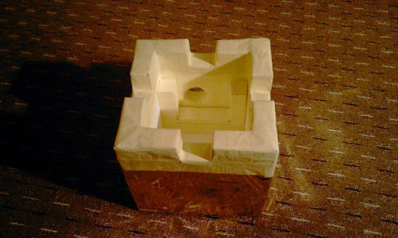
I stripped the box of the thermal blanket and covered it with the masking tape. With the transmitter inside the box, the acquisition of the signal took a little longer (a few minutes), but unlike with the thermal blanket on, it  got the GPS signal locked. Thus I finally had a working tracking solution.

Sunday 28 September 2014

The New Tracking Solution

The idea to track the balloon with the help of an antenna throughout the flight was there, but the knowledge and the experience with this field were not. Thus once more, I turned my attention to Google search looking for existing transmitter solutions and to physics textbook for the theoretical background. Not knowing what terms to look for, my search took a detour to tracking wildlife only to return back to finally finding a couple of websites describing tracking devices right for high altitude balloons.

The specific parts often differ, but the overall concept usually looks like this. A microcontroller (often some model of Arduino), a GPS module (one of the Ublox modules for example) and a transmitter (like Radiometrix's NTX2). All of this put together and programmed properly is capable of transmitting its GPS position (plus whatever you want it to transmit) that you receive via an antenna connected to a radio. For the powering purposes, a few AA batteries are used with the capacity of about 10 hours (this figure relates to my specific solution).
This is how it may look all put together. Arduino Nano, Ublox NEO-6M, Radiometrix NTX2, 6 AA batteries.
But transmitting the balloon's position is only a half of the story. On the other side of the transmission, you need to be able to receive it somehow. For this, I had to build an antenna (in my case I chose a 9 element Yagi for 434MHz) and find a way to process the signal. Since I didn't want to invest too much in a regular radio, I returned to Google. Luckily, I stumbled upon something called SDR (more on that later).

The Intermission

The previous articles described the work I did from April 2013 to the end of August 2013. At this stage, I had the balloon basically prepared. So for the first couple of weeks of September, I waited only for the right wind conditions. But with the autumn approaching, they never came. After that, I went away for a month and left all the thoughts concerning the flight behind.

Another impulse to finish the job didn't come until the summer of 2014 approaching. The main news being my decision to replace the HTC sending an SMS tracking system with a transmitter sending GPS coordinates throughout the whole flight. That began roughly a three month period of studying, googling, building and testing. All of that leading to the launch in September 2014.

Saturday 27 September 2014

The Balloon

After weighting the payload, I gained a figure important for further calculations. The principle behind the balloon's flight is simple. The balloon gets filled with helium. Helium at the same pressure has lesser density than air, thus applying upward directed force on the balloon. As the balloon ascends, the air pressure decreases allowing the balloon to expand. The helium within the balloon expands as well, and thus its density decreases too. With this happening throughout the ascent, the balloon keeps its buoyancy. The limit for this cycle is the balloons ability to expand. Each balloon has a specified burst diameter. After reaching this limit, the balloon bursts and the payload falls back to the earth slowed down by the parachute.
Since I wanted the balloon to reach 30 kilometers, I wrote a few calculations into an Excel spreadsheet. I googled the values for air and helium density at different altitudes up to 39km. I found the expected burst diameters for different balloons as stated by the manufacturer. The different balloons are named based on their weights. So you can come across a Hwoyee 800g balloon, Totex 1200g balloon and so on up to 3000g, I think. The weight of the balloon is positively correlated with its burst diameter. Totex and Hwoyee are the manufacturers then.
Here is the table of balloon weights (600g-3000g) and their corresponding burst diameters (6.02m-12.00m). I chose the amount of helium and the balloon's and payload's weights as my inputs. First, I would calculate the volume of an idealized sphere of helium based on its initial weight (the weight is a constant in these calculations) at different helium densities (the values I googled corresponding to the different altitudes). From the volume, I could then calculate the sphere's diameter thus getting the balloon's expected diameter at the specific altitude.
For the values eventually used, I got the burst altitude some 300-400m short of the desired 30km. Another important number is the amount of free lift or consequently the ascent speed. In following calculations, I summed the weights of the payload (0.9kg), the balloon (0.8kg) and the helium. Out of this, I got the downward heading force acting on the balloon. If I had matched that force by the upward directed force of buoyancy, I would have made the whole balloon float. But I needed it to ascend. That is why, I had to add some amount of free lift. The overall lift force is simply the weight of the air displaced by the balloon times the acceleration of gravity (9.8). From the difference of the two forces acting on the balloon, I gained the resultant force heading upwards. Using the drag equation with this force as an input and a drag coefficient of 0.5, I could find the ascent speeds for different altitudes. Then I simply averaged them to get a single number. This value with the expected speed of descent is then used in trajectory predictors like the CUSF Landing Predictor.

To sum up the logic at play here. More helium in the balloon leads to faster ascent speed, shorter flight and thus the possibility of the balloon landing closer to you. But at the same time it means that the balloon will burst at a lower altitude. On the other hand, too little helium might result in the balloon, due to lack of the lift force, ending up floating and not reaching the burst altitude which is a problem if you want to recover the payload.
Based on these calculations, I had an idea of what sort of a balloon I needed. Now, the problem was getting it. I searched and googled and found no high altitude balloon seller in the Czech Republic and just a couple of in the US. Ordering the balloon from the US meant basically doubling the price and when I finally found a decent opportunity on Amazon, they didn't send to the Czech Republic. In the end, I managed to find a seller in the UK and order one Hwoyee 800g. The shipping cost wasn't great, but at least I finally had the balloon.
 
Once I had the balloon and the calculations done, it was time to think about how to fill it with the right amount of helium. As always, I sought inspiration in other projects. One way of accomplishing the task is to use a bottle filled with water tied to a filling hose. The filling hose is then equipped by a plastic tube at the end. The tube is used for attaching the balloon. This whole apparatus (including the water) should weigh exactly as much as the payload and the amount of free lift one desires. As the balloon fills with helium, it starts to pull on the apparatus lifting it from the ground. When it achieves this floating state one has the desired lift force.
Filling the balloon was one of the things I was a little afraid of, because it's not possible to practice it properly. The balloon is fragile, so it is advised to use latex gloves when handling it. As always, I looked for some verified method how to do this. The used tools are usually a tape, a string and some plastic strap fasteners.
First, you insert your filling tube into the balloon's thicker filling part. Then you secure it with one or two strap fasteners and the tape. The pictures are just for illustration. In reality, there would be much more tape. After that, you let the helium fill the balloon.
Once the balloon with the apparatus floats, you enclose the balloon with another pair of strap fasteners right above the end of the filling tube. You can help yourself with a string too. It's also advisable to cover the plastic straps with tape, so no sharp edges can pierce the balloon. After that, you take off the filling tube and reeve the end of the balloon through the cord to your parachute. Then you secure the folded ends of the balloon together with some more plastic straps, strings and tape. That should be it and the balloon should be securely anchored to your parachute cords.

I should explain why I in my calculations settled for an expected burst bellow the 30km altitude. It is necessary to state that the calculation is just the best guess. The current state of the atmosphere differs, or the individual balloons may be more resilient (and the experience from both mine and other projects suggests that it is often so). Aside from my own calculations, I used other estimating algorithms found on the internet to give me some feedback, and the truth is, they all differed a little bit. Some used different values for air or helium density and so on. The bottom line is that the calculations are just the best guess, but the reality will be most likely a little different.

Friday 26 September 2014

The Payload Arrangement

Having all the devices tested and prepared, it was the time to put it all together. I started with carving out a hole in the side of the box and creating a polystyrene frame for the camera. The camera should be tightly pinned to the hole, so as little cold air as possible can get inside the box. Coincidentally, I managed to find a flat plastic circle that exactly matched the dimensions of the camera's objective. I stuck it around the hole in the box, thus when placing the camera in position it would stick close to the camera's body allowing only the lens out. And once again I used a lot of the masking tape to cover the crumbling polystyrene.
 
Another device that needed to peek out of the box was the thermometer. The external probe is attached to the end of a fairly long cable, so I drilled another hole, this time, in the opposite wall of the box.
After that, everything was ready to be inserted in. The camera went to its frame, plus I prepared another polystyrene segment to separate it from the rest of the box. To the opposite wall, I placed the thermometer with its probe sticking out of the box. To secure it in its place, I used pieces of foam cut to fit the free space. The last device was my phone. The HTC HD2 is fairly thin, so I placed it inbetween a vertical piece of foam and the polystyrene wall separating the camera.
And all of this was covered by the two top pieces of polystyrene described in The Box article.
Here are all the parts together. The only things missing are the balloon and my HTC which is being used to take the picture.
Now that I had everything that would be hung below the balloon, I could measure its total weight. The empty box with the straps measured 250g, the parachute with the cords 180g, the Canon A2200 135g, the HTC HD2 157g, the S0122 datalogger 120g and some weight was added on by all the polystyrene and foam fillings. All in all, the total weight was 900g to be lifted by the balloon to the desired 30 kilometers.

Thursday 25 September 2014

The Thermometer

When I started planning the project, I wanted to get some data from it back. One sort of data was the GPS and altitude information, another was temperature. The balloon with its intended reach up to 30km above sea level promised data from a not so ordinary and regularly achievable environment.
The device I eventually used was Comet System's S0122 datalogger. It is able to measure and record temperatures every 10 seconds from both an inbuilt sensor and an external probe in the range of -50 to +150°C. Thus I would have a record of the outside temperature with respect to altitude and a record of to what conditions was the inner equipment exposed.

The idealized International Standard Atmosphere model states a gradual decrease in temperature from the sea level's 15°C  to -56.5°C in the altitude of 11km. Then a stable temperature from 11 to 20km followed by a gradual increase in temperature from 20 to 47km altitude. That promised a proper test for the payload box and the equipment inside.

Wednesday 24 September 2014

The GPS (HTC HD2)

This is a description of the initial solution I had for finding my payload after the flight. At that time, I wanted to do the tracking as trivially as possible. So once again inspired by an article about an iPhone tracked balloon, I decided to head in this direction. The phone I had at hand was my HTC HD2 powered by Windows Mobile 6.5 system. Although, I was already using a GPS app to track my runs and bike rides, I had to search for an app that was able to send the GPS coordinate via SMS to another phone and to do so automatically. Some time with Google search eventually led me to an app called ReliRescue. It was capable of acquiring the current GPS position and based on the preset interval periodically sending SMS messages to a selected number. Exactly what I needed.
And here is the received SMS message.
Naturally, I first did a couple of tests. The most important question for me was whether the app can keep functioning even when the phone loses either the GPS signal or the GSM signal. From what I understand, the GSM signal reaches to an altitude of 2 km at best and the GPS signal is altitude restricted as well depending on the device used. (In a later article I will describe a GPS module that with the right settings is able to function up to 50 km above sea level.)
This is a map of the signal coverage of my phone provider. This was something to take into account when choosing the right wind conditions for the flight. Ideally, the balloon's predicted landing site should lie in an area covered by the signal. In this case, I used it for my testing as well. I chose some spots without the signal close to my home and rode there on my bike. Turning on the app, I kept riding in and out of the signalless area and observed it's behavior. The app functioned fine, so I proceeded to testing the GPS signal.With that I simply turned the app on, went to the basement and put the phone into a freezer where it lost the signal. Then I went out again and saw the app acquiring the position again thus confirming its functionality.
One more app I intended to use in the flight was GPS Cycle Computer. As I said, I use this app to track my runs and bike rides and in the same way I wanted to use it to track the balloon's trajectory. Because with the ReliRescue app, I would only get the final landing position without ever discovering where the balloon was during its flight.
With all the tests done, the flight would go like this. I would turn on the apps. Set the SMS sending cycle to, let's say, 15 minutes. Wait for the first SMS to arrive to verify that everything is working as it is supposed to. Put the phone inside the payload and launch it. Then, I would have to wait for about 3 hours or possibly more without any clue about the balloon's fate, because it would be beyond the GSM signal coverage and perhaps beyond the GPS signal as well. And then, hopefully, after reentering the signal domain, the balloon would eventually send me its GPS position. Not very comforting, I know, so I equipped the payload box with some contact information should someone find it first or should the tracking system fail altogether.

One more thing about the ReliRescue app. For some reason it has preset functionality only up to September 2011, or something like that. So if you want to use it now, you'll have to change the date and time of your phone into the past, pre-September 2011.